Project Planning Manual SIPART DR20
Planning example S6
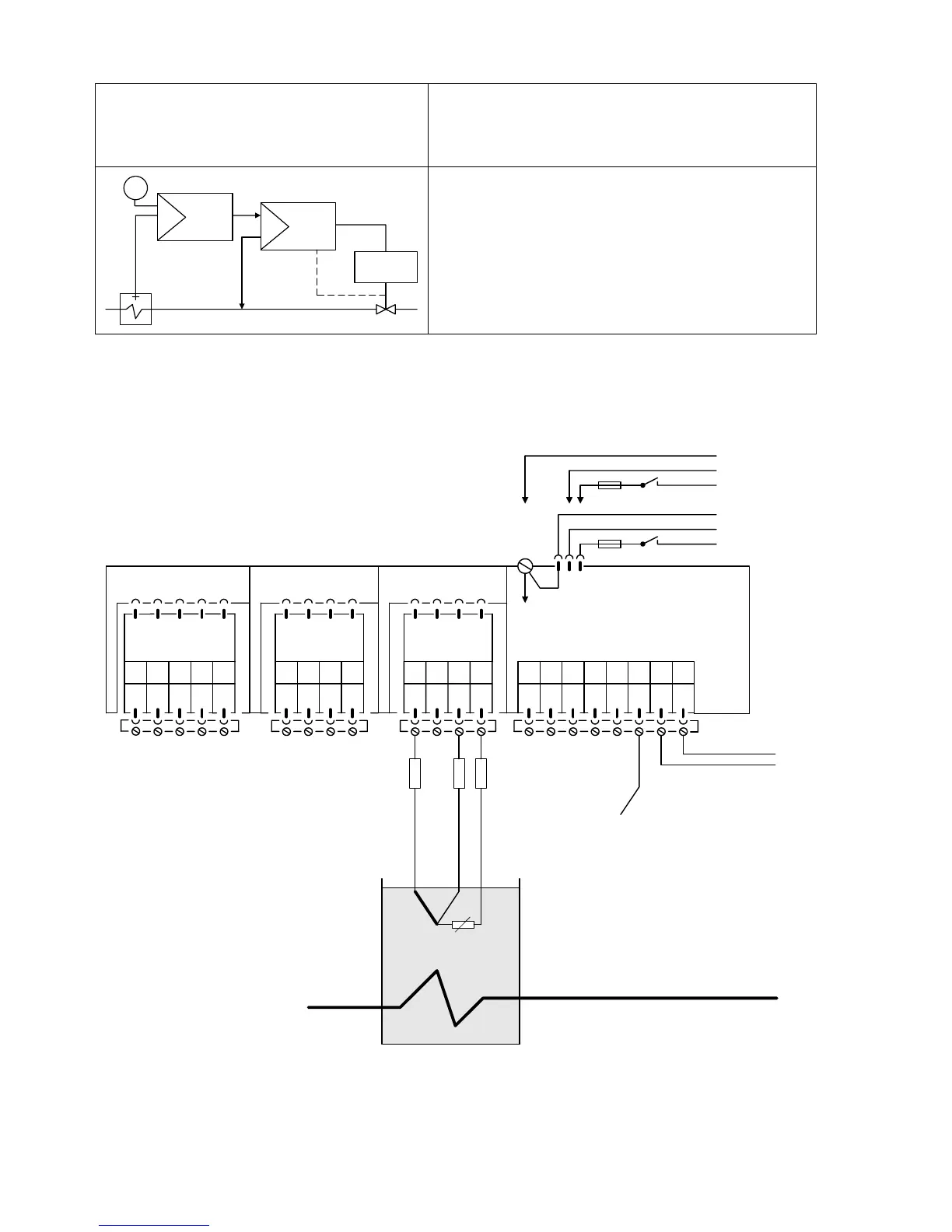
Cascade control
Process variables for both controllers from
resistance thermometers Pt 100
W
y
Drive
Y
R
Master
Slave
The master controller has a continuous output, the
slave controller is a three-position step controller.
The resistance thermometers are directly connected
to the analog inputs AE3 of both controllers.
The output signal of the master controller is the
remote setpoint of the slave controller and linked to
its analog input AE2.
Please refer to the remarks on page 108 and the note on page 15 !
Setting of configuring switches: S8 = 1
AE1 AE2 BE BA L+ GND GND Iy
12345678
SIPART DR20 K
6DR2004-1 (AC 230 V)
6DR2004-2 (AC 115 V)
6DR2004-4 (UC 24 V)
123412341234
PE
N
L
AC 115 V
AC 230 V
⎫
⎬
⎭
PE
N
UC 24 V
L
⎫
⎬
⎭
Slot 3 GW Slot 2 AE4 Slot 1 AE3
5
M1 A1 R1 A2 M2
not equipped
M M/A S E
Option module
6DR2800-8P
R
L1
R
L3
R
L4
Pt100
Master controller
not equipped
R
L1
= R
L3
= R
L4
≤
50
Ω
130

 Loading...


