7SJ61/62/63 6MD63 - Modbus
C53000-L1840-C001-01
6-1
6 Modbus register map
Modbus register map
6
6.1 Explanation
Note
The examples shown in this chapter 6.1 do not necessarily correspond
to the real allocation of the objects in the register mapping.
Chapters 6.3 to 6.6 define the mapping of the data objects of the
SIPROTEC devices 7SJ61, 7SJ62, 7SJ63 and 6MD63 to the associated
Modbus registers.
There are three standard mappings (standard mapping 1 to standard
mapping 3) available, which have an identical data size and differ in the
scaling of the measured values (ref. to chap. 6.5).
The listed SIPROTEC data objects are sorted by register addresses
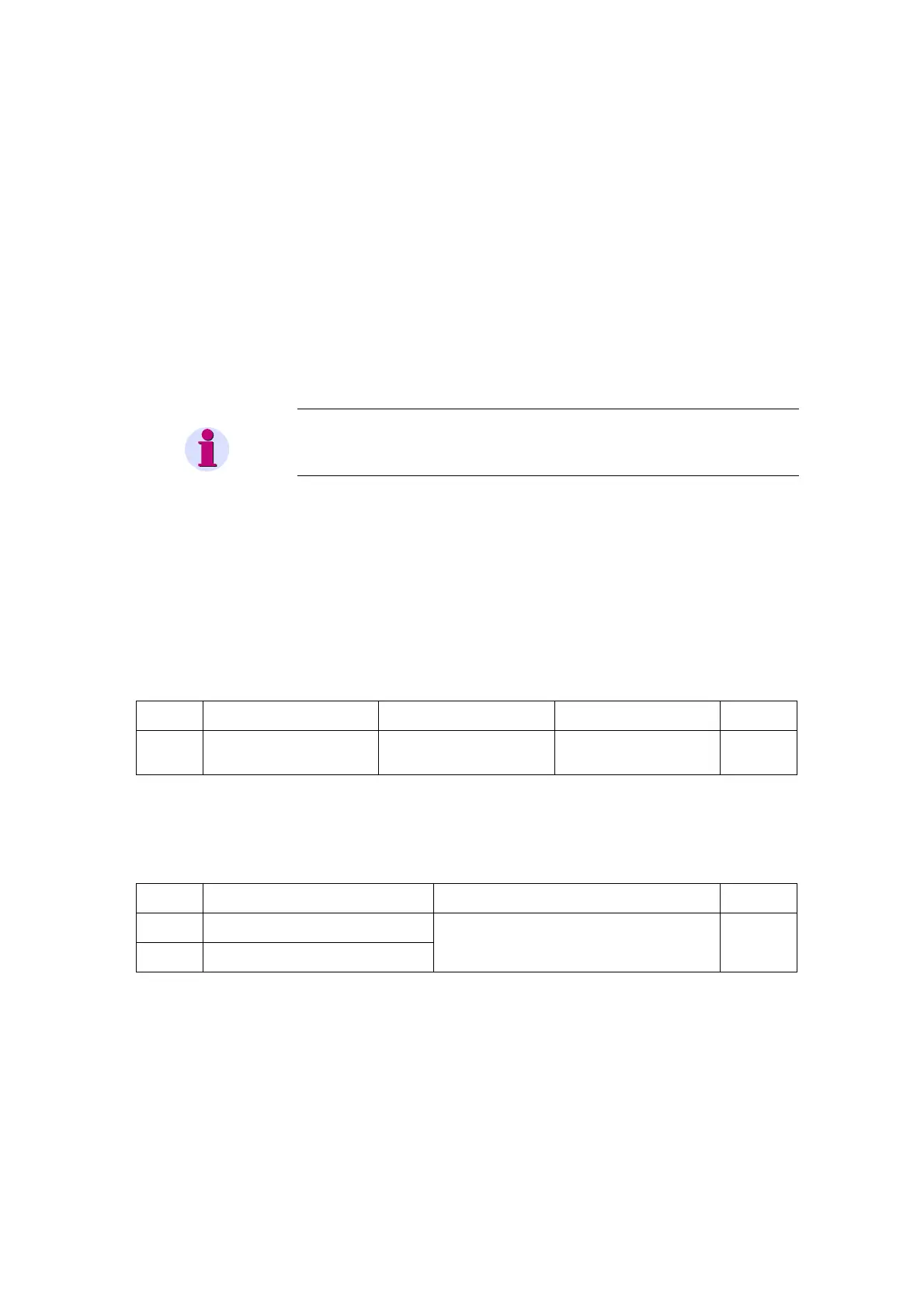
(starting with 1), e.g.:
Register
address
Designation of the
SIPROTEC objects
Comments
Scaling
(32767 corresponds to ...)
Internal
object no.
30001 IA Current in phase A 1: 3276,7 A
2: 32,767 kA
3: 3276,7 A
601
The measured value “IA“ (ref. to chap. 5.3 for measured value data type
definition) is assigned to register 30001 (input register).
Register
address
Designation of the
SIPROTEC objects
Comments
Internal
object no.
00001 Q0 ON/OFF
ON
00002 Q0 ON/OFF
OFF
Circuit breaker –
The double command "Q0 ON/OFF" and simultaneous the checkback
indication of the circuit breaker Q0 as an double-point indication (ref. to
chap. 5.2 for data type definitions) are assigned to the coil status
registers 00001 (ON) and 00002 (OFF).

 Loading...


