Modbus register map
7SJ61/62/63 6MD63 - Modbus
C53000-L1840-C001-01
6-21
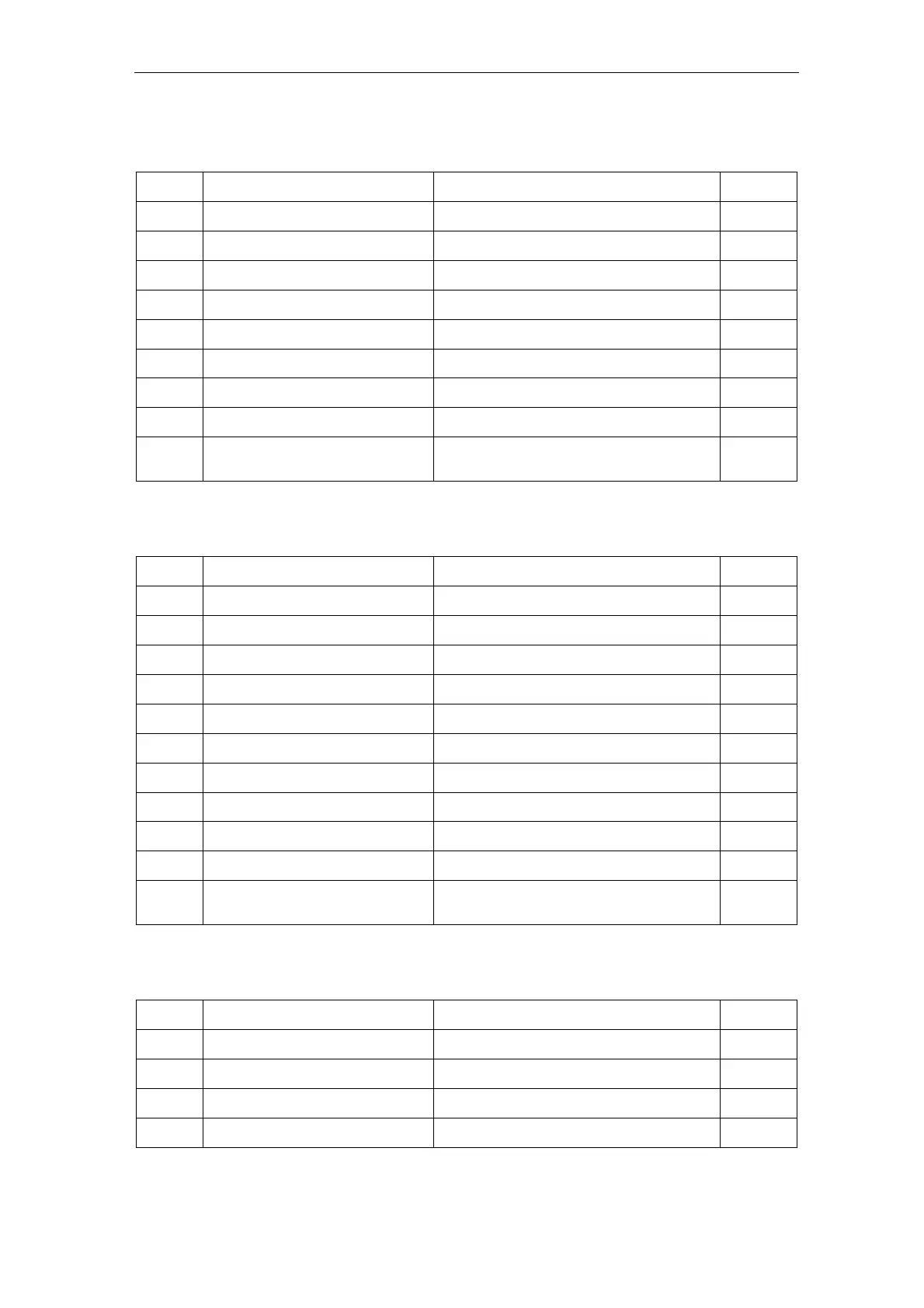
6.4.18 Register addresses 10401 to 10408: Measurement supervision
Register
address
Designation of the
SIPROTEC objects
Comments
Internal
object no.
10401 Fail I Superv. 1 = Failure: general Current Supervision 161
10402 Failure <sum> I 1 = Failure: Current Summation 162
10403 Fail I balance 1 = Failure: Current Balance 163
10404 Fail V balance 1 = Failure: Voltage Balance 167
10405 Fail Ph. Seq. 1 = Failure: Phase Sequence 171
10406 Fail Ph. Seq. I 1 = Failure: Phase Sequence Current 175
10407 Fail Ph. Seq. V 1 = Failure: Phase Sequence Voltage 176
10408 MeasSup OFF 1 = Measurement Supervision is switched OFF 197
10409
–
10416
reserved
4
–
6.4.19 Register addresses 10417 to 10426: Set point alarms
Register
address
Designation of the
SIPROTEC objects
Comments
Internal
object no.
10417 SP. Op Hours> 1 = Set Point Operating Hours 272
10418 SP. I A dmd> 1 = Set Point Phase A dmd> 273
10418 SP. I B dmd> 1 = Set Point Phase B dmd> 274
10420 SP. I C dmd> 1 = Set Point Phase C dmd> 275
10421 SP. I1dmd> 1 = Set Point positive sequence I1dmd> 276
10422 SP. |Pdmd|> 1 = Set Point |Pdmd|> 277
10423 SP. |Qdmd|> 1 = Set Point |Qdmd|> 278
10424 SP. |Sdmd|> 1 = Set Point |Sdmd|> 279
10425 SP. 37-1 alarm 1 = Set Point 37-1 Undercurrent alarm 284
10426 SP. PF(55)alarm 1 = Set Point 55 Power factor alarm 285
10427
–
10432
reserved
4
–
6.4.20 Register addresses 10433 to 10446: Status annunciations
Register
address
Designation of the
SIPROTEC objects
Comments
Internal
object no.
10433 >Trig.Wave.Cap. 1 = >Trigger Waveform Capture 4
10434 >Reset LED 1 = >Reset LED 5
10435 >Set Group Bit0 1 = >Setting Group Select Bit 0 7
10436 >Set Group Bit1 1 = >Setting Group Select Bit 1 8

 Loading...


