Drive functions
5.3 Closed-loop velocity control
Hydraulic Drive
150 System Manual, 04/2015, 6SL3097-4BA00-0BP1
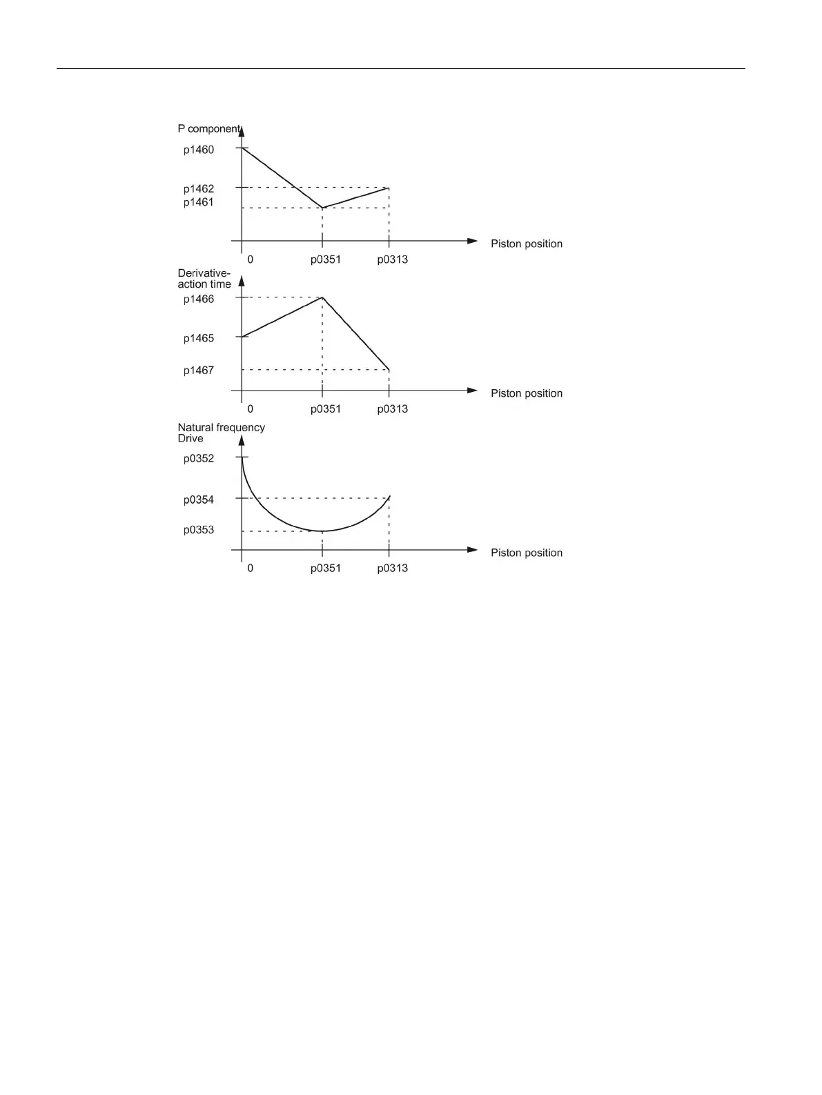
Figure 5-7 Adaptation
A graphic representation of the relationships can be found in Figure 5-8 Function diagram
4965 - velocity controller (Page 155).
The natural frequency of the drive varies as a function of distance. Extreme values occur at
the two limits and approximately at the center (p0351) of the traversing range. It may
therefore be useful to adapt the velocity controller position (P and D components), with the
extreme range limits specified as interpolation points.
If the piston zero has not been calibrated, the adaptation will not be effective, even if it is
activated.
When adaptation is active, the P gain and D action component of the velocity controller are
interpolated linearly between two points.
"Calculate controller data" alters the settings for the controllers and the adaptation selection.
A negative P gain setting may be useful for oscillation damping (p1460 or p1462). The gain
is specified in relation to the drive servo gain setting. 100 % means that for a setpoint-actual
value difference having the magnitude of the maximum velocity (p1083, p1086), the full rated
valve voltage is output as P component.
The P gain, set with p1461, refers to the controlled system gain set using p1475.
 Loading...


