Commissioning
3.4 Sensor Installation
FUP1010 IP67 Portable Quick Start
Operating Instructions, 01/2013, CQO:QSG003 Revision 05
29
11. Slide sensor into a mounting frame back end first aligning the angled edge of the sensor
with the angled edge of the mounting frame. Keep sensor from making contact with the
pipe until it butts up against the mounting frame stop. Push sensor down to mate with
pipe.
12. Tighten the sensor clamping screws to hold the sensor firmly in place.
Repeat procedure
for the other sensor
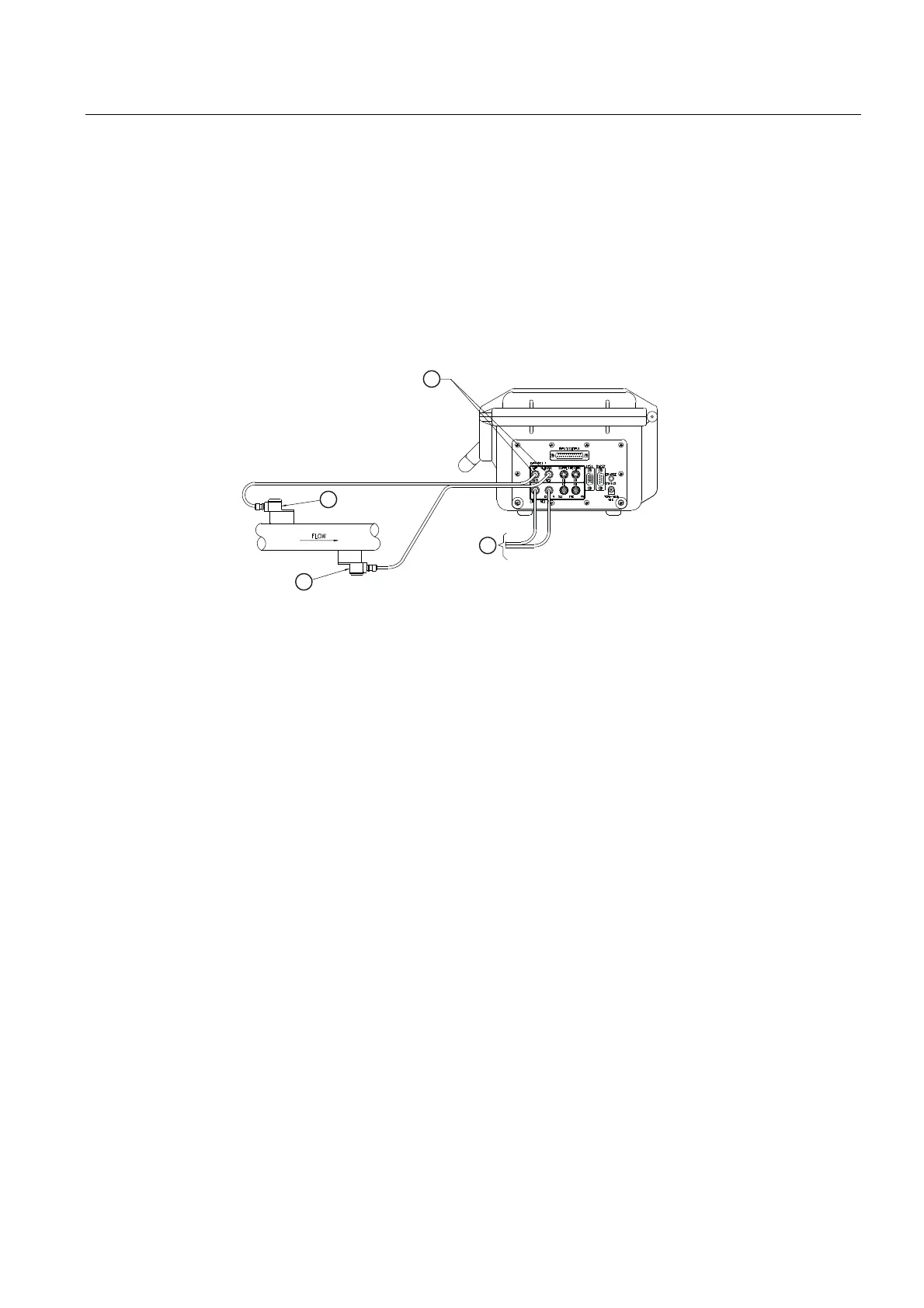
13. Observing the upstream and downstream orientation, attach the UP and DN cables to the
sensors and make snug. Attach the other ends to the UP and DN terminals of the (see
figure below).
① Flow Sensor Cable Connectors ③ Channel 1 - Upstream Sensor
② To Channel 2 Flow Sensor Set ④ Channel 1 - Downstream Sensor
Figure 3-9 Connecting Sensors to Flow Meter
3.4.3 Final Setup
1. At [Install Sensor] menu, scroll down to [Install Complete]. Press the <Right Arrow> and
select [Install]. Press <ENTER>. Flow meter will go through drives.
2. Observe the Measured Vs window and verify a correct sound velocity measurement (if
known).
3. Press the <Down Arrow> to accept sound velocity value.
4. The meter is now ready to report flow. Press the <MENU> key twice to display flow.

 Loading...


