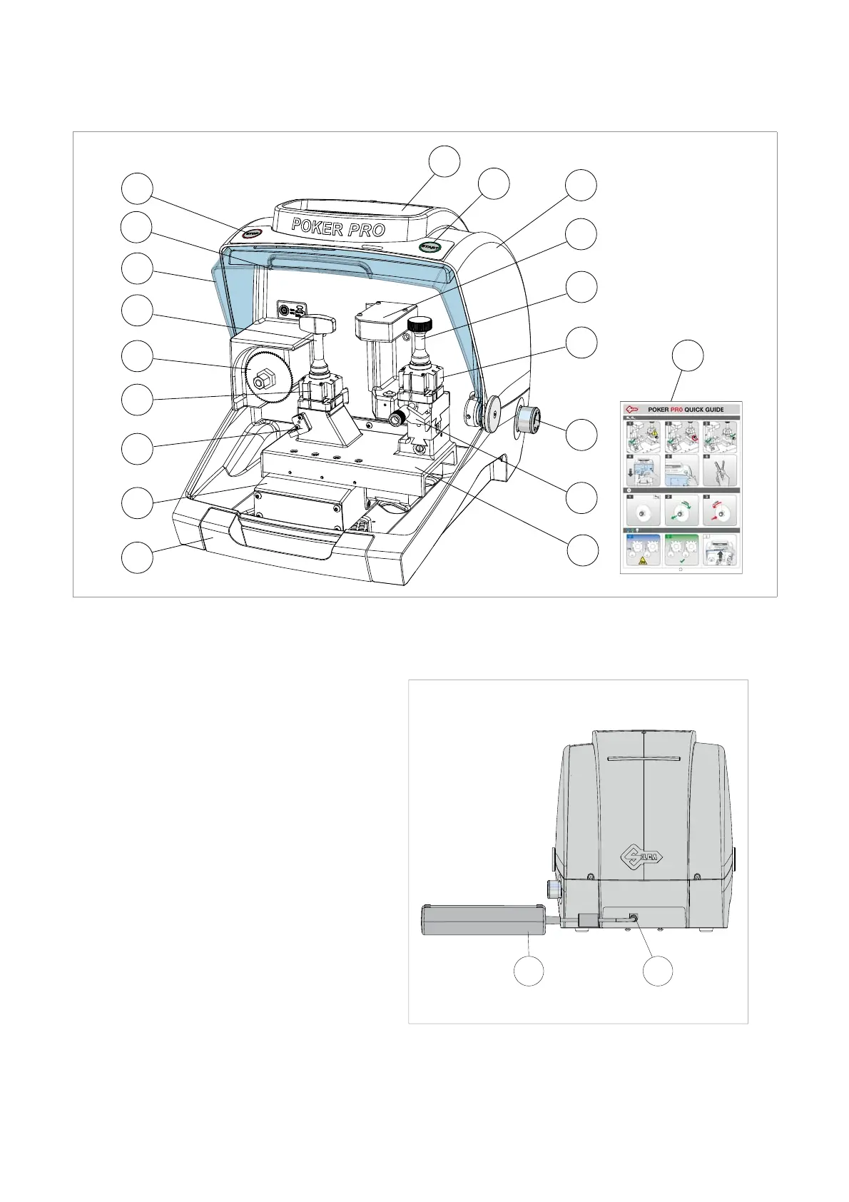
1.1 MAIN OPERATING PARTS
P
M
F
C
B
L
A
N
K
M1
P1
H
E
Z
R
Q
S
S
D
Fig. 3
A
- START button
B
- STOP button
C
- Safety shield
D
- Lamp
E
- Cover
F
- Prismatic cutter
H
- Optical reader
L
- Tool compartment
K
- Swarf collection tray
M
- Clamp - cutter side
M1
- Clamp knob - cutter side
N
- Key gauge - cutter side
P
- Clamp - optical reader side
P1
- Clamp knob - optical reader side
Q
- Key gauge - optical reader side
R
- Pulsante accensione/emergenza
S
- X axis carriage
T
- Y axis carriage
W
- Power pack
W1
- Power pack connector
Z
- Quick Guide
W W1
Fig. 4
Operating manual POKER PRO
Copyright Silca 2019
5