Camera power requirements.
The camera can accept a range of input voltages, as follows:
Input voltages 14-36VDC or 14-26VAC.
(Low-power mode available on some non-IR models.)
Power 45W – [60W IR models.]
These figures do not include the requirements of any optional heating or cooling devices added within the camera, nor
optional infra-red lighting systems.
Power supply units are available for both mains feeds and low voltage DC automotive power sources.
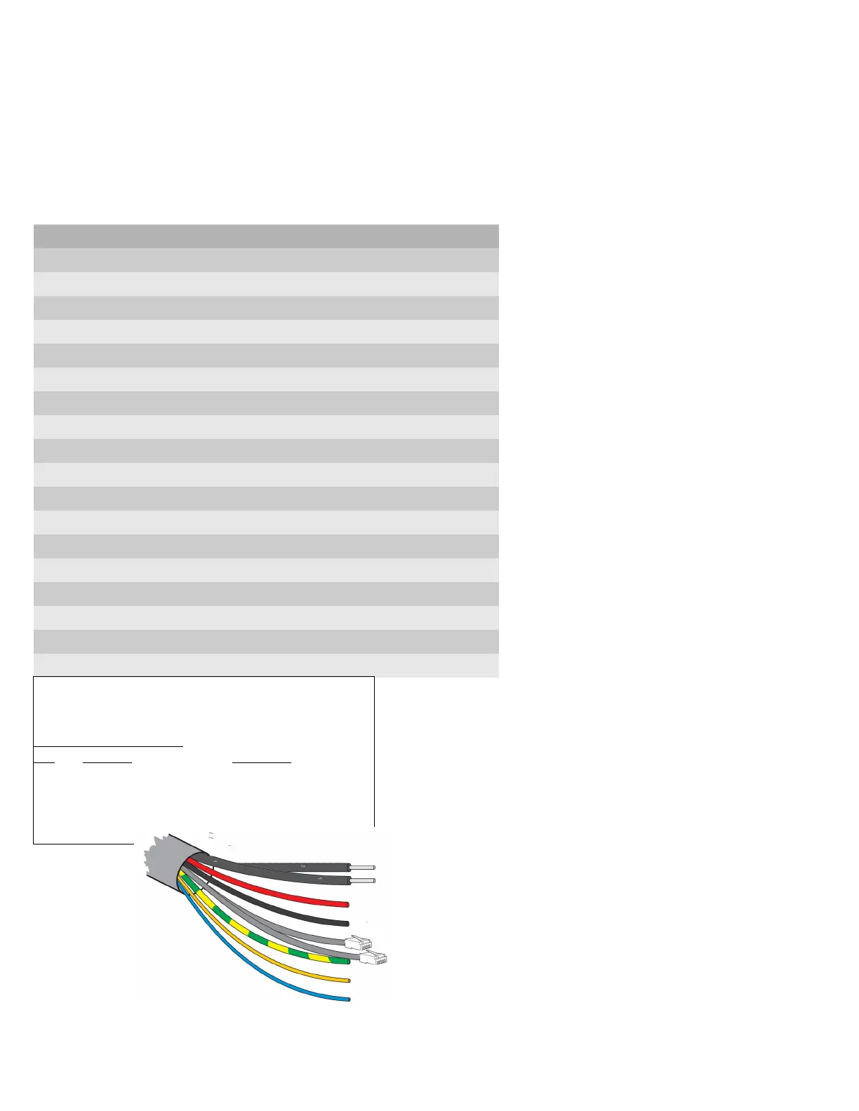
Multiway Connector / Cable allocations. (CA-UCM / CA-U14CN)
A Power + Red
B Power - Black
C Video 1 Signal Coax 1 Core
D Video 1 Ground Coax 1 Screen With OSD Menu text display
E Aux Pos Orange Wash pump relay closing contact
F Aux Neg White Wash pump relay closing contact
G RS-485 Data + UTP Yellow (opt. Green)
H RS-485 Data - UTP Blue
J Earth Green/Yellow stripe Common to pin M Earth
K Video 2 Signal Coax 2 Core With OSD Menu text display
L Video 2 Ground Coax 2 Screen
M Eth 2 - Rx- - Net2 – Second IP (OSD/Thermal)
N Eth2 - Rx+ - Net2 – Second IP (OSD/Thermal)
P Eth1 - Rx- Cat5 Green Net1 – First IP (HD)
R Eth1 - Rx+ Cat5 White/Green Net1 – First IP (HD)
S Eth2 - Tx+ - Net2 – Second IP (OSD/Thermal)
T Eth1 - Tx- Cat5 Orange Net1 – First IP (HD)
U Eth1 - Tx+ Cat5 White/Orange Net1 – First IP (HD)
V Eth2 - Tx+ - Net2 – Second IP (OSD/Thermal)
Co-axial: Composite Video (mini RG59).
(Two video connections on some models)
Red: Power Positive (Live).
Black: Power Ground (Neutral).
Cat5: Netwok connections.
Green+Yellow: Chassis Earth.
Yellow (Green): RS-485 Telemetry (Data+).
(sleeving Green on some models)
Blue: RS-485 Telemetry (Data – ).
Grey: Cable Screen.
Orange and White Auxiliary conductors on some models.
Closing contact pair for Washer relay triggering.
1.0 Power and Signal connections.
The network interface is through the RJ45
Ethernet connectors to be plugged to a LAN
switch, router or local computer network interface.
The No.1 connector provides the HD Colour
camera feed.
On models with two imagers the second
connector provides the second camera feed, e.g.
Thermal view. This is provided through the
Alternat pairs of the Cat5 bundle.
The second network feed will also provide viewing
of the OSD Menu display within the image
.
PTZ control can be through either IP interface*
(* Not on all models and can be VMS dependant)
Netwok connection leads.
Cat5/8P8C pinout configuration – 10/100BASET
(TIA568B)
Network connectors 1.
Pin Colour Function
1 White/Orange TX D1+
2 Orange TX D1 -
3 White/Green RX D2+
6 Green RX D2 -
RS-485 connection addressing.
Please note that the PTZ address (Pelco D)
is fixed at Address ID: 001.
If the direct RS-485 connection is used the
PTZ should not be connected to other
CCTV camera equipment as address
clashes may occur.
This should only be used for test and
configuration activities.