Il collegamento elettrico va eseguito
all'interno del pannello comandi
della caldaia. Per i dettagli consultare
lo schema elettrico della caldaia
Per le pompe vedere i morsetti di appoggio in caldaia
SC
A6
MD
MB
M
DB
B9
B10/70/4
B3
B2
H1
F1
Q1
Q3/y3
L
N
N
L
ALBATROS RVA43.222
P2
E1
K5
F5
K4
F4
Verso comandi accensione
I° e II° stadio bruciatore
vedere schema elettrico caldaia
SR SC
A6
MD
MB
M
DB
B9
B10/70/4
B3
B2
H1
F1
Q1
Q3/y3
L
N
N
L
ALBATROS RVA43.222
P3
E1
K5
F5
K4
F4
Verso comandi accensione
I° e II° stadio bruciatore
vedere schema elettrico caldaia
–+ –+
LPB BUS Non invertire la polarità della connessione
A6
MD
MB
M
DB
B9
B10/70/4
B3
B2
H1
SE
F1
Q1
Q3/y3
L
N
N
L
ALBATROS RVA43.222
P1
E1
K5
F5
K4
F4
Verso comandi accensione
I° e II° stadio bruciatore
vedere schema elettrico caldaia
SM
–+
PB
SC
SB
A6
MD
MB
M
DB
B9
B1
F2
Y1
Y2
L
N
N
L
ALBATROS RVA46.531
PZ2
Q2
F6
–+
UA2
A6
MD
MB
M
DB
B9
B1
F2
Y1
Y2
L
N
N
L
ALBATROS RVA46.531
PZ1
Q2
F6
–+
UA3
PPS BUS
PPS BUS
–+–+
MASTER SLAVE 1
SLAVE 2
H1
ZONA 1
SZ
VM
A6
MD
MB
M
DB
B9
B1
F2
Y1
Y2
L
N
N
L
ALBATROS RVA46.531
PZ3
Q2
F6
–+
VM
SZ
UA1
PPS BUS
–+
ZONA 2
ZONA 3
H1
H1
TMAX
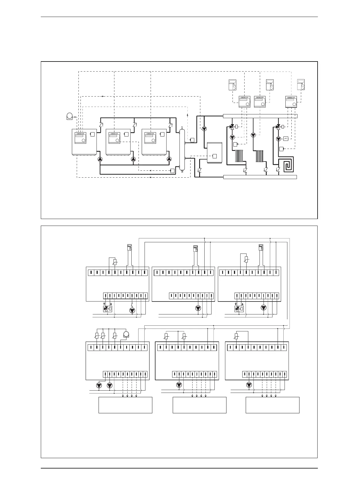
3.7.1 SYSTEM I7 - 2/3 boiler cascade with external hot water tank and 3 zones controlled by a mixer valve, pump and floor system
Hydraulic circuit
* For information on RVA46.531 unit
refer to the product’s manual
LEGEND
SM Cascade delivery probe (QAD21)
SE Outdoor temperature probe (QAC31)
SB Hot water tank probe (QAZ21)
SI Hydraulic separator
SR Cascade return probe (QAD21)
PI
1-2-3 Boiler pumps
BP Bypass
UA
1-2-3 Zone room unit (QAA70)
PZ
1-2-3 Zone pumps
TMAX Overheating thermostat
SC Boiler delivery probe (QAZ21)
SZ Zone Boiler (QAD21/QAZ21)
VM Three-way mixer valve
IP Floor system
PB Hot water tank pum
Wiring diagram
hot water tank
(separate)
Wiring must be performed inside the
boiler’s control panel. For details plea-
se refer to the boiler’s wiring diagram.
Do not invert connection polarity
Toward burner stage 1 and 2 igni-
tion commands Refer to boiler
wiring diagram.
Toward burner stage 1 and 2 igni-
tion commands Refer to boiler
wiring diagram.
LEGEND
SM Cascade delivery probe (QAD21)
SE Outdoor temperature probe (QAC31)
SB Hot water tank probe (QAZ21)
SR Cascade return probe (QAD21)
PI
1-2-3 Boiler pumps
PB Hot water tank pump
UA
1-2-3 Zone room unit (QAA70)
PZ
1-2-3 Zone pumps
TMAX Overheating thermostat
SC Boiler delivery probe (QAZ21)
SZ Zone probe (QAD21/QAZ21)
VM Three-way mixer valve
PB Hot water tank pump
For pumps, refer to suporting terminals on the boiler
Toward burner stage 1 and 2 igni-
tion commands Refer to boiler
wiring diagram.