User Manual For - CONTROLLER/DATA RECORDER MultiCon CMC-99/141
Connections of power supply voltage and measurement signals are performed using the
screw connections at the back of the unit’s housing (see
Fig.
4.7
).
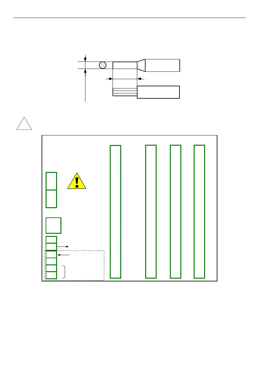
Fig. 4.7. Method of cable isolation replacing and cable terminals dimensions
All connections must be made while power supply is disconnected !
Fig. 4.8. Terminals description
The basic performance of the device (see
Fig.
4.8
) contains only the extreme left
terminals:
– Power supply,
– SERVICE,
– Sensor supply output +24V DC Imax=200mA,
– Digital input 0V...15...24V DC (low state: 0÷1V, high state:8÷24V)
– Interface RS-485,
16
!
5-6 mm
max. 1.5 mm
Slot D
Power supply
(depending on version)
1
2
Slot B
8
5
6
7
3
4
Slot A
Slot C
+24V DC ±5%
Imax. = 200mA
digital input
0/15..24V DC
RS-485
GND
GND
A+
B-
isolated
SERVICE

 Loading...