Home
Simex
Controller
MultiCon CMC-99/141
Simex MultiCon CMC-99/141 User Manual
5
of 1
of 1 rating
332 pages
Give review
Manual
Specs
To Next Page
To Next Page
To Previous Page
To Previous Page
Loading...
User Manua
l For -
CONTROLLER/DATA
RECORDER Mul
tiCon
CMC-99/141
The
propor
tions
of
the
individual
indicators
available
in
the
SCADA
Lite
display
mode
have been
presented in
Tab. 7.7
.
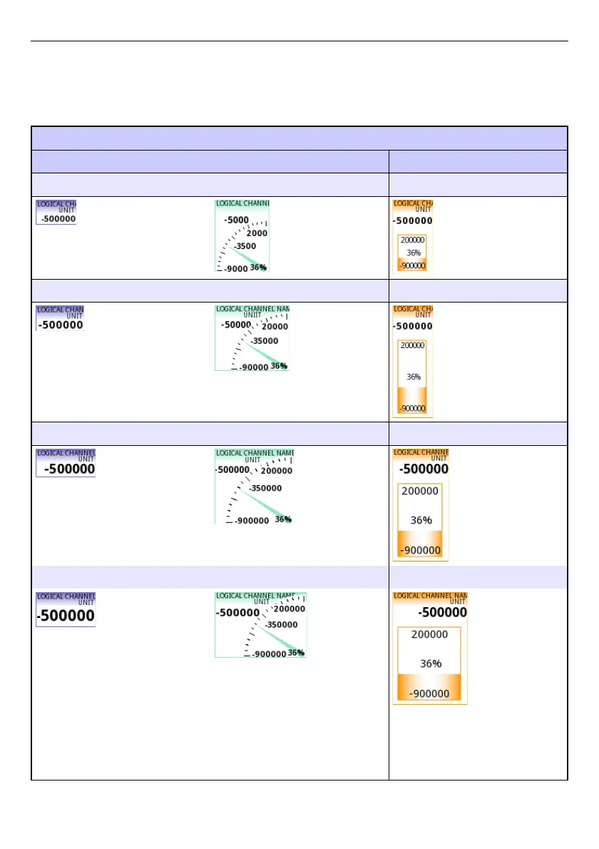
Slot sty
le
value
needle
bar
54x33 px
73x96 px
54x100 px
64x34 px
100x87 px
45x150 px
80x38 px
106x100
px
75x150 px
80x46 px
123x87 px
100x150
px
232
231
233
Table of Contents
Default Chapter
2
Table of Contents
2
1 Basic Requirements and User Safety
5
Touch-Screen Use
6
2 General Characteristics
6
3 Technical Data
9
4 Device Installation
10
Unpacking
11
Assembly
12
Connection Method
14
Available Modules
17
Maintenance
31
5 Introduction to Multicon CMC-99/141
31
Understanding Controller/Data Recorder Multicon CMC-99/141
31
Logical Channels
32
Groups
34
Hardware Configurations
35
6 Working with the Multicon CMC-99/141
36
Multicon CMC-99/141 Power up
36
The Use of the Touch-Screen
36
Display
36
Information Bar
37
Navigation Bar
38
Data Panels
39
Important Messages
42
7 Configuration of the Multicon CMC-99/141
44
Edit Dialogues
44
Main Menu Selection Panel
47
Files Management
48
Device Information, Licence, Firmware Update, Remote Display, Export Manual and Renew Configuration
58
Device Configuration
62
Configuration Menu Structure
65
General Settings
71
Logical Channels
75
Logical Channels - General Settings
75
Logical Channels - Hardware Input Mode
94
Logical Channels - Hardware Output Monitor Mode
97
Logical Channels - Modbus Mode
99
Logical Channels - Set Point Value Mode
102
Logical Channels - Math Function Mode
105
Logical Channels - Controller Mode
115
Logical Channels - Profile/Timer Mode
117
Logical Channels - Profile/Timer (Cycle Counter) Mode
119
Logical Channels - Data from Other Channel Mode
120
Examples of Logical Channels Configuration
121
Application of the Logical Channel in the Hardware Input Mode for the UI4 Module
121
Application of Logical Channel in the Hardware Input Mode for TC4 Modules
128
Application of Logical Channel in the Hardware Input Mode for RT4 Modules
131
Application of Logical Channel in the Hardware Output Monitor Mode for R45
134
Modules
134
Application of Logical Channel in the Modbus Mode
136
Application of Logical Channel in the Hardware Input for TC8 Modules
138
Application in Math Function Mode
140
Application of Logical Channel in the Controller Mode
142
Application of Logical Channel in the Profile/Timer Mode
144
Application of Logical Channel in the Hardware Input Mode and Data from Other Channel for FT4 Module
146
Built-In Inputs
148
Built-In Inputs - General Settings
148
Built-In Inputs - Input Modules
150
Built-In Inputs - Binary Input Inp.x2 : Digital 24V
150
Built-In Inputs - Demo Input Numbered X3, X4, X5
151
Built-In Inputs - Modules
152
Voltage and Current Measurement Modules
152
Mixed UIN/UID Modules
152
Isolated Current Inputs Module
154
Analogue Flowmeter Modules
154
Pulse Flowmeter Modules
155
Thermocouples Sensor Measurement Modules
157
RTD Measurement Modules
158
Isolated Universal Inputs Modules
158
Optoisolated Digital Inputs Modules
159
Optoisolated Universal Counters Modules
160
Optoizolated Hourmeters Modules
161
Built-In Outputs
163
Built-In Outputs - General Settings
163
Built-In Output - Relays, Sound Signal, Virtual Relays
165
Built-In Output - PWM (Pulse-Width Modulation) Mode for SSR Relay Output
169
Built-In Output - Current Output
171
Examples of Build-In Output Configurations
173
Application of the Output for R45 Modules
173
Application of Output for IO Modules
175
External Outputs
177
External Outputs - General Settings
177
External Outputs - Control Type: as a Relay
179
External Outputs - Control Type: as a Linear Output
180
Examples of External Output Configurations
183
Application of External Output for Protocol Modbus in the MASTER Mode
183
Profiles/Timers
186
Profile/Timer - General Settings
186
Profiles/Timers - Triggering Mode: Level (Gate), Edge (Once), Edge (Retrig.)
191
Profiles/Timers - Triggering Mode: on Time
193
Examples of Profile/Timer Configurations
195
Application of the Profiles/Timers
195
Application of the Profiles/Timers Triggered on Time
197
Controllers
199
Controllers - General Settings
199
Examples of Controller Configurations
214
Application of the Controllers
214
Application of the Controllers in Cooperation with Heater Which Is Controlled by SSR Output
215
Groups
218
Groups - General Settings
218
Groups - Logging Options
224
Groups - Examples of Visualisations of Groups
225
Single Channel - One Big Needle
225
Three Channels View - One Bigger, Two Smaller
226
Groups - Scadalite
227
Modbus
234
Modbus - General Settings
235
Modbus - SLAVE Mode
236
Modbus SLAVE - Modbus Templates for SLAVE Mode
237
Modbus SLAVE - Device Channels for SLAVE Mode
238
Modbus SLAVE - the Modbus Protocol Handling
239
Modbus SLAVE - List of Registers
239
Modbus SLAVE - Transmission Errors Handling
241
Modbus SLAVE- Example of Query/Answer Frames
241
Modbus - MASTER Mode
242
Modbus MASTER - Device Templates Parameter Block
243
Modbus MASTER - Device Channels Parameter Block
244
Modbus MASTER - Register Settings
246
Modbus MASTER - Register Blocks Parameter Block
246
Modbus - Example of Modbus Protocol Configuration in the Device
248
Input Configuration of Modbus Protocol in MASTER Mode
248
Configuration of the Modbus Input in the MASTER Mode
251
Network and Remote Display Settings
254
Access Options
256
Printouts
260
E-Mail Notifications
262
8 Appendices
265
Ps3, Ps4, Ps32, Ps42 - Power Supply Module
265
Ui4, Ui8, Ui12, U16, U24, I16, I24 - Voltage and Current Measurement Modules
266
Ui4N8, Ui4D8, Ui8N8, Ui8D8 - Mixed Uin/Uid Modules
272
Is6 - Isolated Current Inputs Module
274
Fi2. Fi4, Ft2, Ft4 - Flowmeter Modules
276
Tc4, Tc8, Tc12 - Thermocouple Sensor Measurement Modules
279
Rt4 , Rt6 - Rtd Measurement Modules
282
Un3, Un5 - Optoisolated Universal Inputs Modules
285
D8, D16, D24 - Optoisolated Digital Inputs Module
291
Cp2, Cp4 - Optoisolated Universal Counters Modules
293
Hm2, Hm4 - Optoizolated Hourmeters Modules
296
S8, S16, S24 - Solid State Relay Drivers Modules
298
R45, R81, R65, R121 - Relay Modules
302
Io2, Io4, Io6, Io8 - Passive Current Output
304
Communication Modules
308
Multiprint Mlp-149 - External Printer
309
General Characteristic
309
Technical Data
309
Working with Multiprint MLP-149
310
Data Format
315
Direct Access to Log Files Using Http Protocol
325
Www Page
328
Menu
329
Documentation
330
Logging and User Menu
330
5
Based on 1 rating
Ask a question
Give review
Questions and Answers:
Need help?
Do you have a question about the Simex MultiCon CMC-99/141 and is the answer not in the manual?
Ask a question
Simex MultiCon CMC-99/141 Specifications
General
Brand
Simex
Model
MultiCon CMC-99/141
Category
Controller
Language
English
Related product manuals
Simex multicon cmc-99
300 pages

 Loading...