7 - 89
7 Transmission Repair
7D Hydro-Gear 0750 / 0800
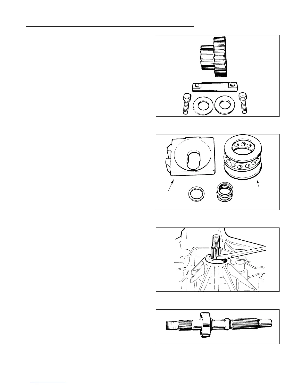
33. Remove the motor thrust bearing assembly, swash-
plate kit and cradle bearings from the housing and
inspect for unusual wear or damage.
34. Remove the slot guide block from the displacement
control shaft.
35. Remove the bypass actuator from the housing.
Figure D–23.Swashplate & Thrust Bearing Assembly
Figure D–24. Remove Input Shaft Seal
Figure D–25. Pump Input Shaft Assembly
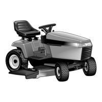
Figure D–22. Jack Shaft/Pinion Gear Components
29. Inspect the jackshaft running surface for excessive
wear or damage. The jackshaft should be 0.4986” to
0.4996”.
30. Inspect the pinion gear bore for excessive wear or
damage. The bore should be 0.5014” to 0.5024”.
31. Inspect the pinion gear teeth for excessive wear or
damage.
32. If excessive wear or damage was found, the com-
plete assembly should be replaced.
36. Reposition the housing and remove the input shaft lip
seal from the housing bore. A hook type tool may be
used to pry the seal out. Care must be taken to avoid
damage to the housing bore, shaft sealing surface or
bearing. Once removed, the seal is not to be reused.
37. Remove the input shaft bearing retaining ring.
38. Remove the pump and input shaft assembly from the
transaxle housing.
39. Inspect the shaft and bearing for unusual wear or
damage.
40. Reposition the housing and remove the displacement
control shaft and lip seal.
41. Inspect the housing for damage.
Thrust
Bearing
Assm.
Guide
Block
Bypass Actuator
 Loading...