Configuration and setup
20221495F 101
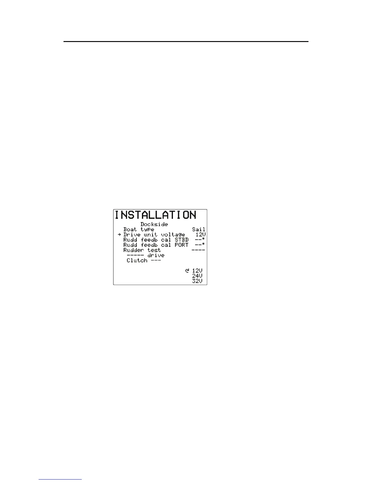
Drive unit voltage
Set the drive unit voltage to correct level. The selections are
12V, 24V, or 32V and should be set to the voltage specified for
your drive unit.
Refer to the drive unit table on page
72 for information.
The drive engage/bypass clutch output follows the same voltage
as set for the drive unit. It is not possible to select a higher
voltage than the input voltage.
Caution ! Selection of improper voltage level for your drive unit may
damage both the drive unit and the autopilot computer even if
the protection circuits in the autopilot computer are activated.
During the Rudder Test, the AP25 system will automatically
detect whether the drive unit is a reversible motor or a solenoid
is operated.
To change the voltage
selection, rotate the course
knob.
Note ! The drive unit voltage setting does not apply when operating
solenoids on a continuous running pump/steering gear. Hence,
the output voltage to the solenoids will be the same as the input
voltage.
Proceed to next menu item by pressing STBD button.
Rudder Feedback Calibration
Make sure the RF300 is installed and aligned as pr. instruction in
section
3.6 (or eventually section 3.27 for LF3000). This
function enables you to compensate for any non-linearity in the
transmission between the rudder and the rudder feedback.