Installation
20221495F 69
Note ! Due to space limitations, it may be necessary to cut the length of
the transmitter rod to move the RF300 closer to the rudder post.
Tighten the mounting screws for both the RF300 feedback unit
and the transmitter rod ball joint.
Observe the RF300 while someone turns the helm wheel through
the complete travel from full port to full stbd. rudder to verify
that the mechanical linkage to the RF300 is not obstructed.
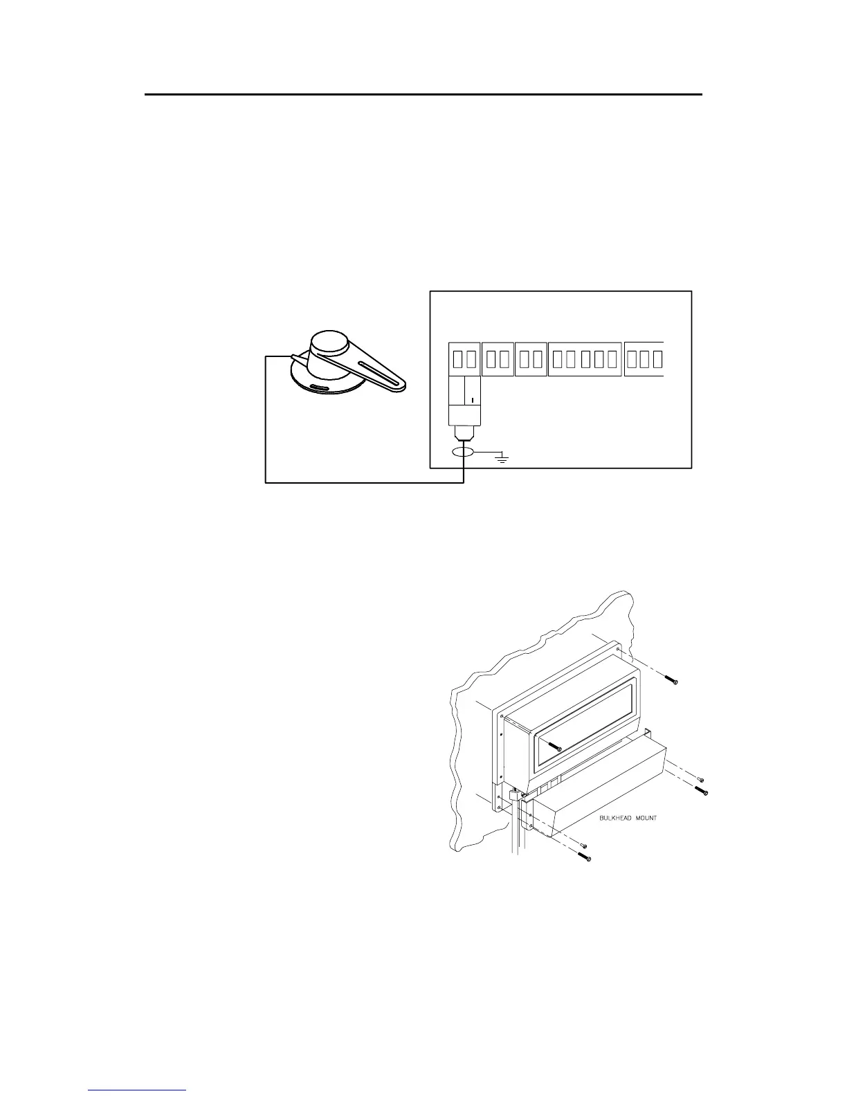
AUTOPILOT COMPUTER
MAIN PCB
Rudder
Feedb.
*
* NON POLARIZED
(COLOR INDEPENDENT)
RF +
RF
Figure 3-3 RF300 connection
3.7 Autopilot computer installation
The autopilot computer is
designed to operate in a
location that provides
ambient temperatures
below +55°C (+130°F).
Note ! The autopilot computer
units (AC10, AC20 and
AC40) are not
weatherproof and should
be mounted vertically as
shown in a dry place
between the control unit
and the drive unit.
Figure 3-4 Autopilot computer mounting