INSTALLATION
20222360 / E 13
Mechanical Installation
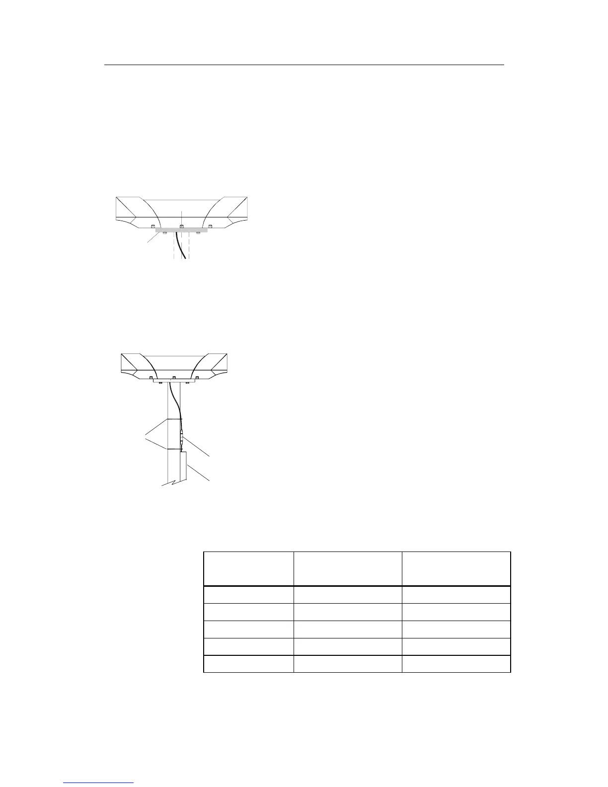
The Sensor unit may be mounted in the mast or directly on the
deck.
The dimensional drawing for the Sensor unit on page 64 shows
dimensions and internal distance for the mounting holes and the
cable outlet.
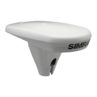
Holder
If necessary, a user-made holder may be used as
shown on the figure when installing the unit.
Caution! Independent of which fastening method that is used, the
Sensor unit should not differ more than ±5° from the vessel’s
horizontal plane and the alongship axis. If the mounting is not
within this tolerance, the heading accuracy will be degraded.
Connectors with
Cable duct
Cable ties
self-bonding tape
Connect the cable from the Processing unit to
the cable from the Sensor unit.
Caution!
The connector junction must be sealed with
self-bonding tape for waterproofing. After
coiling, make bonding by hard pressure.
Use the required number of cable ties to fasten
the cable to the mast.
Cable Wiring
The wiring for the Sensor unit cable in the Processing unit
terminals is as follows:
Cable Wire Signal Description Processing Unit
No. Label
Screen Cable shield Chassis
4 Transmit COMM+
3 Receive COMM-
2 +24 VDC PWR
1 Power ground GND