7
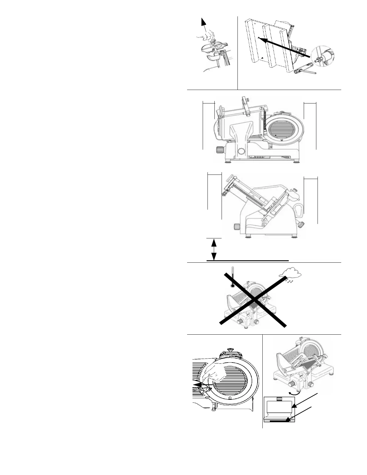
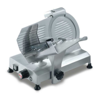
2.2 - POSITIONING
Position the pallet, with the slicer, on a flat
s
urface and remove (a) the cap from the slicer
(Fig. n°12).
Turn the machine on its side (Fig. n°13) and
utilising the correct wrench provided
uns
crew the 4 nuts which secure the slicer to
the pallet. Remove the 4 washers and unscrew
the 4 fastening tie rods on the wooden pallet.
Remove the pallet and fasten the 4 feet provided
to the slicer. Finally, replace cap in its
original
position.
P
osition the slicer in its final operating
location .
The dimensions indic
ated in Tab. 1-2-3 ( which
v
ary depending on model) must always be
c
onsidered and taken into account for when
deciding on the final location of the slicer.
Slicer location must be sufficiently wide
enough to accommodate the slicer, level, dry,
smooth, robust, stable and at a height of
approximately 80 cm from the ground and at
least 20 cm from walls, objects, shelves, etc.
(Fig. n°14) to allow for sufficient room to
operate the slicer respecting and safeguarding
operator safety.
Furthermore, the machine must be located in
an environment with a maximum humidity of
75%, non-saline and with a temperature
ranging between +5°C and +35°C; and in any
event in environments which conform to the above
s
pecifications .
Make sure the graduated hand grip is in position
“0”.
Check alignment of the blade-
thickness gauge by
running a finger (Fig. n°16) from
the blade
towards the thickness gauge (never in the
opposite direction). Unscrew the feet on the
operator’s side until the slicer is correctly aligned
and level. (Fig. n°17).
a
~ 80cm
2
0cm
Fig. n°12 Fig. n°13
Fig. n°14
Fig. n°15
Fig. n°16 Fig. n°17
2
0cm
2
0cm
2
0cm
1
2