8
2.3 - ELECTRICAL CONNECTION
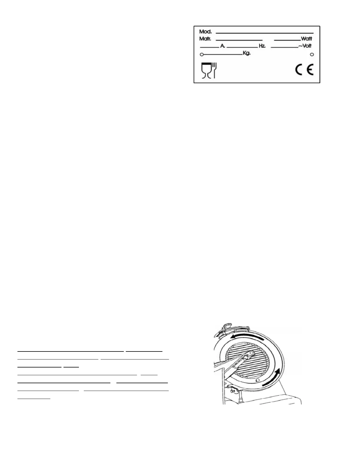
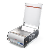
Check that the specifications prov
ided in the
rating plate -serial number (Fig. n°18) and in the
consignment and delivery documents,
correspond; if not contact the supplier immediately.
Check power supply cable and slicer earthing .
2.3.1 - Slicer with single-phase motor
The slicer is fitted with a power supply c
able having a cross section of 3x1mm²; approximate length
1.5m and a “SHUKO” plug. Connect the 230 V - 50 Hz slicer, interposing a 10 A ΔI= 0.03A
thermomagnetic differential switch.
2.3.2 - Slicer with 400 V. three-phase motor
The slicer is fitted with a power supply cable having a cross section area of 5x1mm², approximate
length 1.5m and a red 15A 3F + T CEI plug. Connect the slicer to the 400 V - 50Hz three-phase
supply mains, interposing a 10 A ΔI= 0.03A thermomagnetic differential switch.
2.3.3 - Slicer with 230 V. three-phase motor
The slicer is fitted with a power supply cable having a cross section area of 5x1mm², approximate
length 1.5m and a blue 15A 3F + T CEI plug. Connect the slicer to the 230 V - 50Hz three-phase
supply mains, interposing a 10 A ΔI= 0.03A thermomagnetic differential switch.
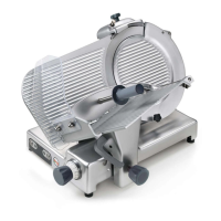
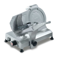
Check blade rotation is anti-clockwise looking at the slicer from bladeguard side. If not proceed as in
2.3.4 .
2.3.4 - Blade rotation direction
To check direction of blade rotation pr
ess the “I”
pushbutton (ON), and then immediately press the
“0” pushbutton OFF.
Blade rotation must be anti-clockwise when
looking at the slicer from bladeguard side
(Fig. n°19). In the event rotation is incorrect ,
invert (Fig.
Fig. n°18
Fig. n°19