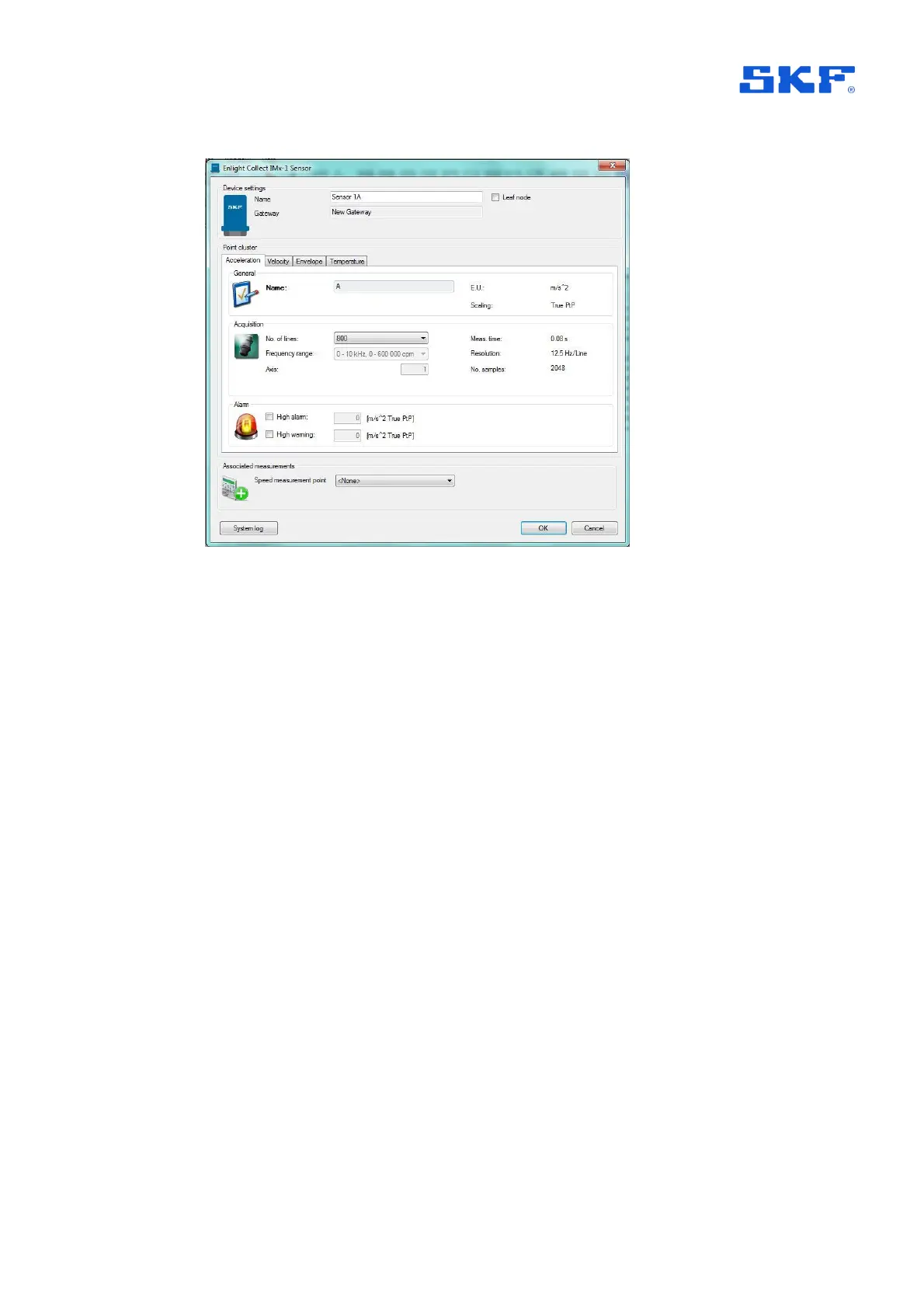
Figure 10 IMx-1 sensor dialog example
Main tab: in the upper area are the sensor ‘Name’ and the ‘Leaf node’ selection,
noting that the node type cannot be changed once the sensor is commissioned.
Name can usefully be used to indicate the sensor’s physical location using standard,
vibration measurement point, taxonomy.
Also provided is a read back of the gateway allocation – ‘Gateway’. For sensors, this
gateway allocation process is indirect, in that measurement sensors are associated
with a machine and in the machine’s properties, it and all its sensors have a gateway
allocated, Figure 16.
Note:
• It is recommended to use the default mesh mode unless it is known that the
sensor location is subject to movement or its ‘wireless environment’ is subject
to temporary interruption by vehicle/machinery movements. In these cases,
leaf mode can be selected.
• Relay nodes, which make no measurements but are there to support/extend
the mesh infrastructure, are created and configured in the IMx-1 System
View.
• Mesh networks auto-adapt but have a rebuild time, therefore:
o Do not activate sensors until they are at their mounting position
On the lower part of the main tab is the possibility to add an associated
measurement. This can only be a software speed point used to associate a machine
speed with the data.

 Loading...
