2018-05-28
Page 11 of 60
Installation DL2 Doppler Speed Log System
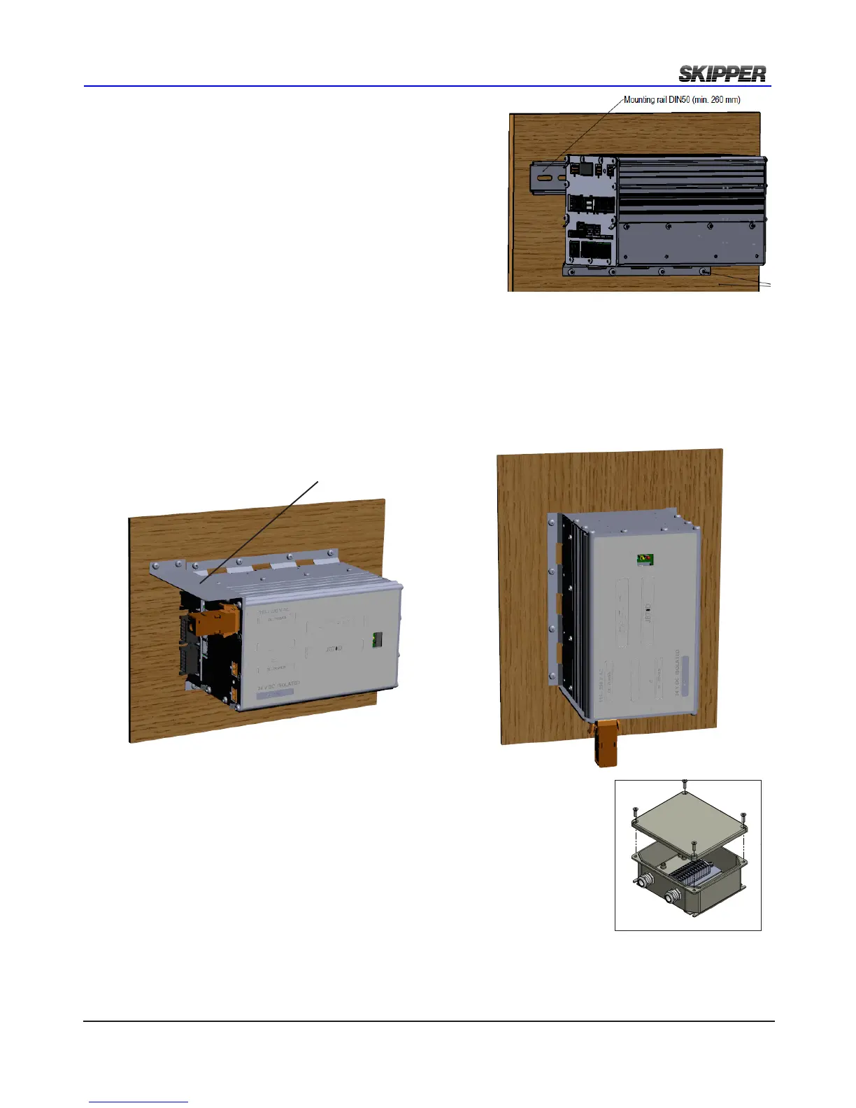
placemenT Of The elecTrOnic uniT
The electronic unit can be installed on a DIN rail or directly
screwed onto the wall.
All parts of the system are connected to the electronic unit.
There are no buttons (like ON/OFF) in the electronic unit.
Access is only required for service purpose.
Placement is typically in or near the bridge where the
interfaced systems are available, but no nearer than 0.5 m
to the GYRO heading sensor.
placemenT Of The elecTrOnic uniT ip22 apprOved
If IP22 is required for electronic unit then:
- Alternative 1
Horisontal installation. PCB’s vertical. IP22 Drip plate installed.
-Alternative 2
Vertical installation
Alternative 1
Alternative 2
Drip plate
Repeaters are typically installed on the overhead console and/or the bridge wings. These can be
routed using NMEA signals. These require a local +24 V DC supply.
66
31,5
165,5
141
161
70
125
144
6,1 (4x)
Approved by - date
HK 2012.02.09
Designed by - date
1 of 1
JB12 Outline Drawing
Scale
OD-JB12
Revision
X0
Sheet
Edition date
Name
Drwg. no.
CN
Checked by
Material
Eur. projection
Gen. tolerance
1:2
ISO2768m
E
D
Electronics AS
B
A
8
7
6
4
D
C
5
1
2
3
A
B
4
3
2
1
C
F
E
placemenT Of Jb12 JuncTiOn bOx
The junction box JB12 is an option for connecting sensor cable to a yard
supplied extension cable (See chapter 3).
It is placed in a dry place within reach of the 40m sensor cable.