Mounting instructions for the sea valve is available from the SKIPPER web site in separate manual
depending on the chosen type. When placing the speed log sensor, consider the following moments:
• Free sight to the bottom (it should be possible to draw a cone of +-45 degrees from the
sensor to the bottom).
• The active face of speed sensor must be in parallel to the horizontal line, max offset +-1°.
• Do not mount transducers aft of bow thruster, propeller outlets or aft of other hull
installations (such as outlets, vents or other protruding details) that may create aeration or
turbulence.
• It is necessary to select a part of the hull that is submerged and free from turbulence and
aeration under all load and speed conditions, and to avoid positions where air is trapped in
heavy weather.
• If a at, horizontal section is not available for transducer tting, the shipyard must construct
a suitable bed. Welding seams in this area and forward should be smoothed and rounded
off in order not to create turbulence or aeration and maintain a laminar waterow at all
speed ranges of the vessel.
• Select an area that is acoustically quiet. The system operates at frequencies between 270
kHz and 284 kHz.
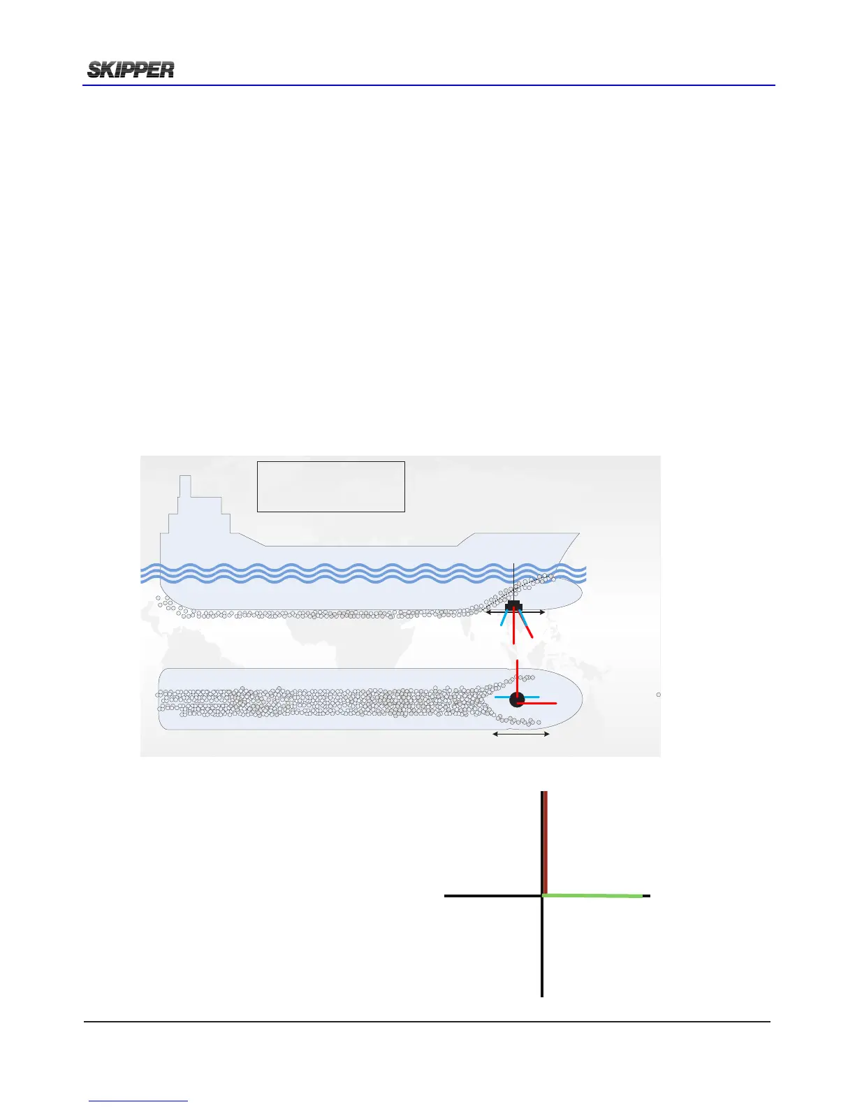
There are 2 channels in DL2.
The acoustic signal is sent in
a 30deg angle in forward and starboard
directions.
In addition a tilt sensor is used to
compensate for vessel movement.
FWD
PORT
STRB
AFT
DL2
Longitudal speed
channel
DL2
Transversal speed
Channel
A
Bubbles
Sensor installation
Bubbles
Side view
Bottom view
Sensor placed
fore
Water relative speed is measured at a depth
between 0.3 and 3 m below transducer.
(DL1)
2 axis Water relative speed is measured at a
depth between 0.3 and 3 m below
transducer. (DL2)
Bottom track is measured down to 150m
depth