Page 16 of 60
2018-05-28
Installation DL2 Doppler Speed Log System
CHAPTER 3: WIRING
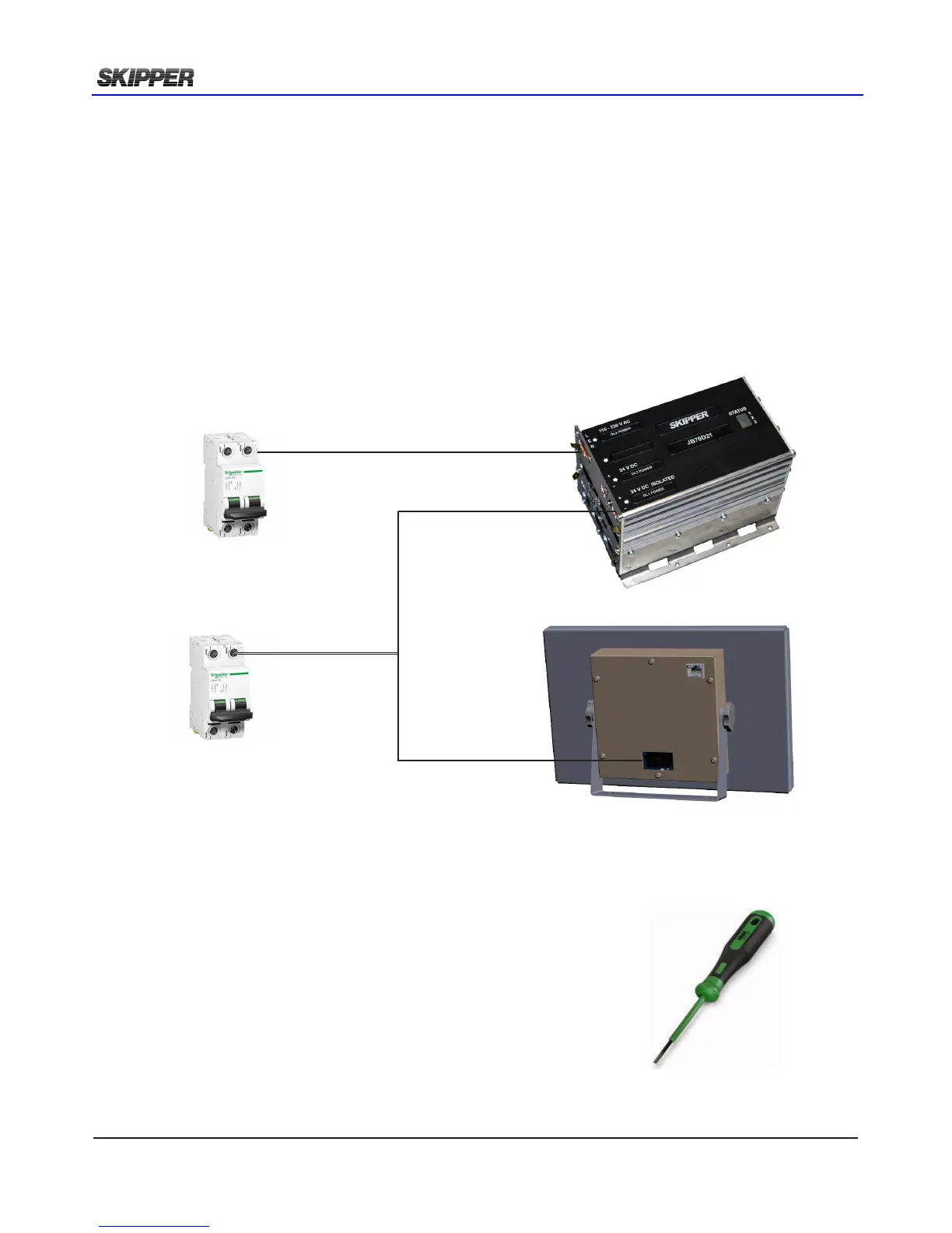
The JB70D2-SA does not contain a physical switch (only software) and should be connected to a
circuit breaker for removal of power.
Power may be nominal 24V DC (No more than 32V DC) and/or 115-220V AC. Max 60W typical 15W.
The AC input is an optional back up for JB70D2-SA only. The operator unit CU-M001-SA requires a
24V DC power supply.
There are no input fuse on the CU-M001-SA or JB70D2-SA.
The power input should be including a fuse rated for 100% - 200% of max power installed components.
Example: A 24V DC to power both CU-M001-SA and JB70D2-SA should have a 3A slow blow fuse.
Cables should be connected to WAGO connector, leaving
approximately 3 cm of tail. They should be stripped with 6-7 mm of
metal showing and these should be connected as in the diagram
above. A small screwdriver with blade size approx 3.5 mm can be
used. WAGO part no 210-719 is ideal for this use.
Outer shields should be collected and grounded in a ground stud on
the edge of the cabinet. The outer insulation should be cable tied to
the plastic handle of the connector, and securely anchored nearby.
The plugs when retted, must be installed such that their clips are
fully in the up position.
220V AC. 0,5A
115V AC. 1A
24V DC. 3A