Page 10
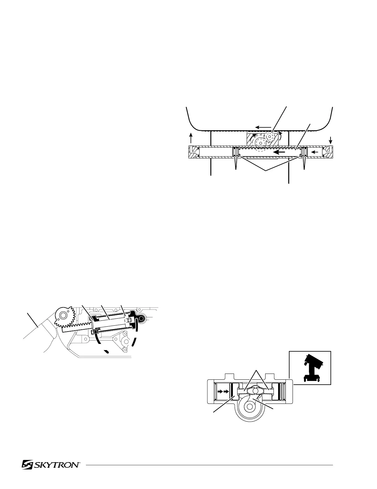
Figure 1-9. Slide Cylinder Assy.
3. Lateral Tilt Assembly - The lateral tilt assem-
bly consists of two cylinders, pistons and connect-
ing rods. The connecting rods attach to the lateral
tilt lever which connects to the table center column
assembly. The cylinder housing attaches to the
table top and is attached to the center column
assembly by pivots. See figure 1-10.
The pistons and connecting rods are attached to a
non-movable surface. Therefore, when hydraulic
fluid is pumped into one side, the cylinder housing
itself moves around the lateral tilt lever causing the
table top to tilt to one side.
To tilt the table top in the opposite direction, fluid is
pumped into the opposite cylinder.
d. Hydraulic Cylinders (Slave Cylinders)
There are several different types of hydraulic cylin-
ders used in the table that activate the control
functions. With the exception of the elevation and
brake cylinders, all operate basically the same
way. The control functions are listed below.
Back Section ------ 2 double action cylinders
Leg Section ------- 2 double action cylinders
Trendelenburg ---- 1 double action cylinder
Lateral Tilt --------- 1 double action cylinder
Elevation ----------- 1 single action cylinder
Kidney Lift --------- 2 double action cylinders
Brakes -------------- 4 single action cylinders
Slide ----------------- 1 double action cylinder
1. Trendelenburg, Back Section and Leg Sec-
tion Cylinders - The double action cylinders are
closed at one end and have a movable piston with
hydraulic fluid on both sides. Connected to this
piston is a ram or shaft that exits out of the other end
of the cylinder. Through the use of a ball and
socket, a gear, or clevis and pin arrangement, this
ram is connected to a movable table surface.
The movable surface can be moved one way or
the other by pumping hydraulic fluid into the cylin-
der on either side of the piston. Obviously, if oil is
pumped into one side of the cylinder, a return path
must be provided for the oil on the other side. See
figure 1-8.
When hydraulic fluid is pumped into one side of the
cylinder, the pistons are pushed in one direction,
the gear arrangement rotates and causes the table
top to slide. Oil pressure can be applied to either
piston, making the table slide end for end. See
figure 1-9.
Figure 1-10. Lateral Tilt Cylinder Assembly
Figure 1-8. Back Section Cylinder
2. Slide Cylinder Assembly - This cylinder
arrangement has two pistons, one on each end of
a ram which has rack gear teeth cut into its top
surface. These teeth mesh with a gear arrange-
ment that drives a rack gear connected to the
bottom of the side frame.
RACK GEAR
82206-109
RAM
O-RINGSO-RINGS PISTONS
82206-108
BACK
SECTION
O-RING RAM PISTON
HYDRAULIC
LINE
HYDRAULIC
LINE
82206-110
LATERAL
TILT LEVER
CONNECTING RODS
PISTON

 Loading...


