Page 45
5-12. Return-to-Level / Positioning Inhibit
Micro-Switches.
The return-to-level feature is activated by a single
button on the pendant control and automatically
levels the major table functions, lateral tilt, Trende-
lenburg, back section, and leg section.
The kidney lift has a back section-up inhibit switch
to prevent the table back section from damaging
the kidney lift when the lift is raised. The back
section still has the capability to be lowered and
raised, but will not raise more than 45° above
horizontal until the kidney lift is completely down. If
the back section is raised more than 45° above
horizontal, the system will not allow the kidney lift to
be raised. An audible alarm will sound if the kidney
lift inhibit switch is activated and either function is
activated - raising back section when Kidney lift is
up or raising kidney bridge when back section is
above horizontal.
The slide function has inhibit switches to prevent
damage to the back and leg sections. If the back
section is below horizontal the top will not slide
toward the foot end. If the leg section is lowered
more than 45° below horizontal the top will not slide
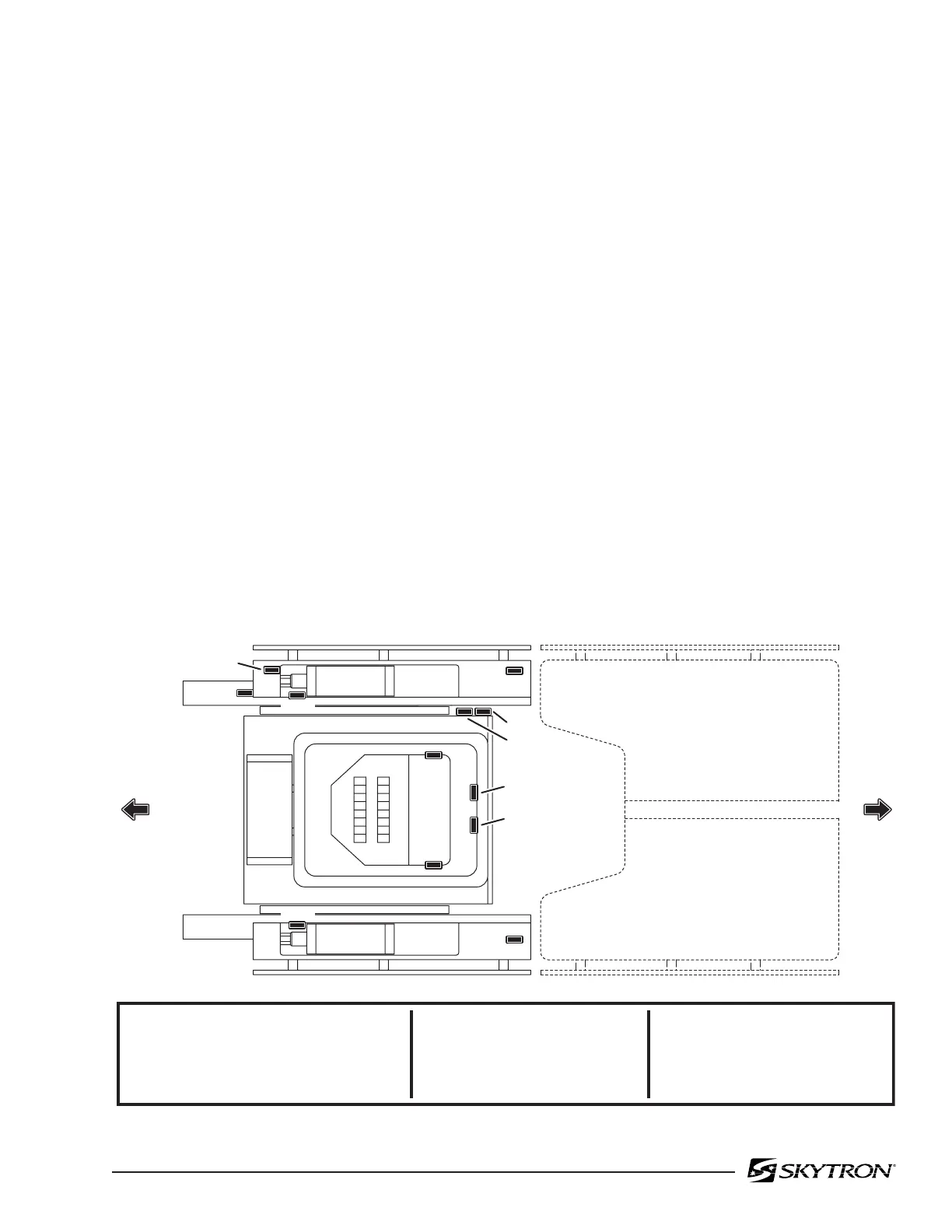
Figure 5-21.
toward the head end. Likewise, if the top is slid
toward the foot end, the back section will not go
below horizontal. If the top is slid toward the head
end, the leg section will not go more than 45° below
horizontal.
The return-to-level / positioning inhibit system con-
sists of 15 micro-switches, 3 electrical connectors,
2 terminal strips and the related wiring. The micro-
switches are mounted on or adjacent to the function
they control and are wired for normally open or
normally closed operation. The micro-switches are
either cam or lever actuated and can be adjusted at
the individual switch mounting brackets. Proper
micro-switch operation depends on all top sections
being properly secured. Check top section fasten-
ers.
The micro-switches operate on low voltage, and
control the function circuits (pump/motor and ap-
propriate solenoid valves) when activated by the
pendant control LEVEL button.
The micro-switches are wired to the relay box
through a riser cord and to the 26 pin connector
CN10. See figure 5-21 for switch location and
identification.
82306-520
CS-5
CS-3
CS-4
NS-7
NS-1
NS-2
NS-4
NS-3
CS-2
CS-1
HEAD SECTION
NS-1
NS-2
NS-3
NS-4
NS-5
TRENDELENBURG
REVERSE TRENDELENBURG
TILT LEFT
TILT RIGHT
BACK-DOWN TO LEVEL/SLIDE INHIBIT
NS-6
NS-7
CS-1
CS-2
CS-3
BACK-UP TO LEVEL
LEG-DOWN TO LEVEL
SLIDE/LEG-DOWN INHIBIT
SLIDE/BACK-DOWN INHIBIT
KIDNEY/BACK 45º UP INHIBIT
CS-4
CS-5
LED-DOWN 45º/SLIDE INHIBIT
BACK-UP 45º/KIDNEY-UP INHIBIT
FOOT SECTION
NS-6
NS-5

 Loading...


