Page 43
5-10. Solenoids
The solenoids are energized by 24 volt potential
that is controlled by the relay box. The solenoid
windings are protected from excessive heat by
an internal thermal fuse that will open after
approx. 7 minutes of continuous operation. The
solenoid must be replaced if the internal thermal
fuse has been blown. The solenoids are mounted
directly on either side of the hydraulic mini-valves
and push the spool valve in one direction or the
other depending upon which solenoid is activated.
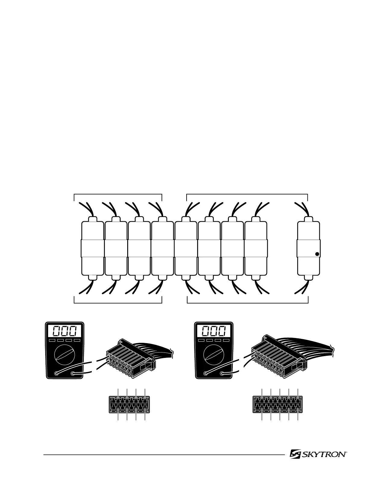
a. Solenoid Test
The resistance of the solenoid coil can be
checked out using an ohmmeter R x 1 scale.
1. Disconnect connectors CN1A and CN1B.
Measure the resistance between the two pins at
the connector for the solenoid in question as shown
in figure 5-17. Polarity of meter leads is not
important.
2. The meter should read approximately 16
ohms at room temperature.
3. Measure the resistance between either
pin and ground.
4. Meter should read infinity.
b. Test Results:
If the solenoid does not check out with the meter,
it is more than likely defective and must be
replaced.
Figure 5-17. Solenoid Test
82306-516
ELEVATION
Up
Down
TREND.
Trend
Reverse
Trend.
LATERAL
TILT
Right
Left
FLEX
Reflex
Flex
BRAKE
Unlock
Lock
BACK
SECTION
Up
Down
Down
Up
KIDNEY
Up
Down
SLIDE
Foot
Head
LEG
SECTION
12 56
CN1A
910 1314
12
15 16 11 12 19 20
34 78
11 12
15 16
3
413
14
910 1718
56
78
CN1B
CN1A
CN1B
1
2
19
20
17
18
15
16
13
14
11
12
9
10
7
8
5
6
3
4
1
2
CN1B
1
2
15
16
13
14
11
12
9
10
7
8
5
6
3
4
1
2
CN1A
BLUE DOT

 Loading...


