Page 6
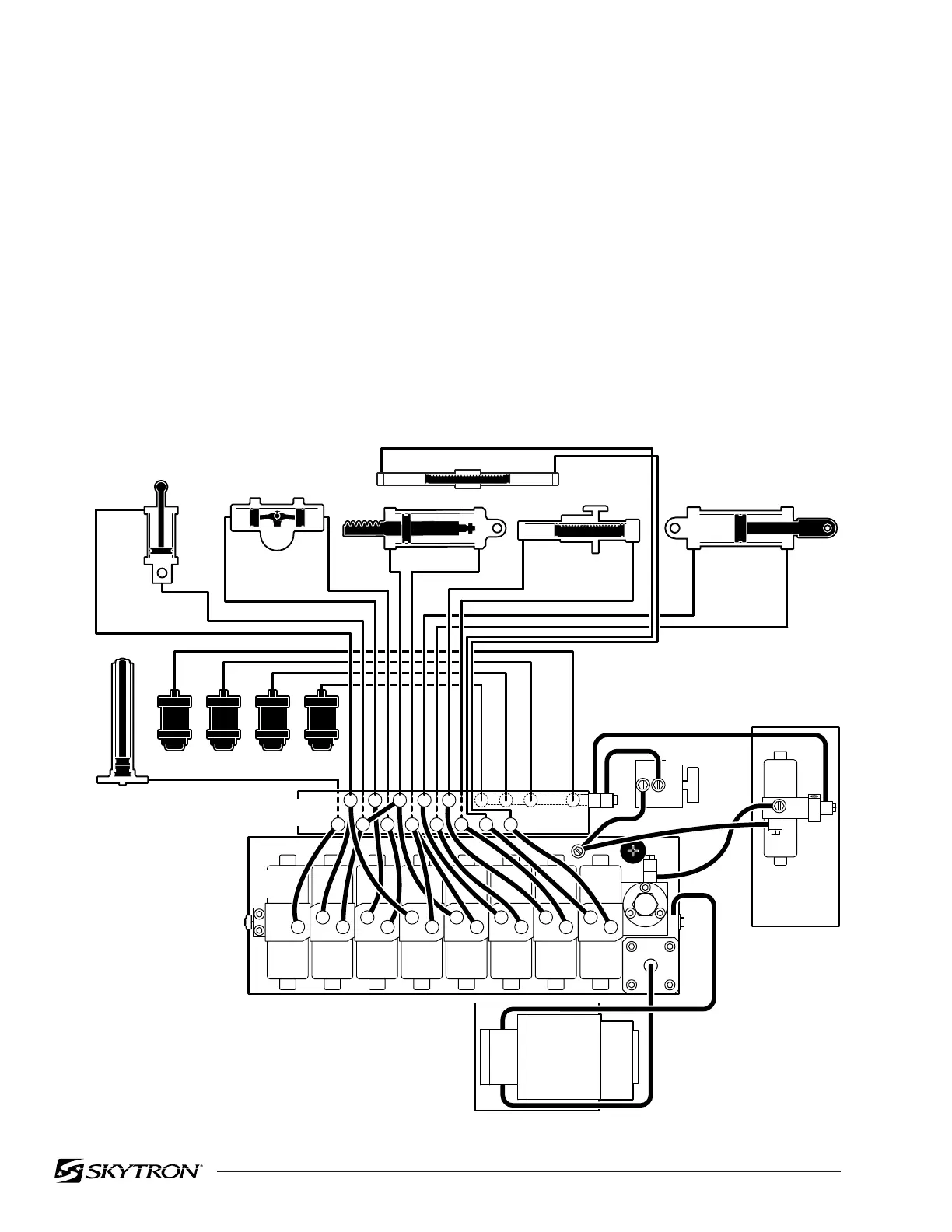
Figure 1-1. Hydraulic Block Diagram
1-1. General
The hydraulic system (with the exception of the
hydraulic cylinders and hoses) is contained within the
base of the table. The hydraulic valves and pump are
electrically controlled by the use of a hand-held push
button pendant control. The power requirements for
the table are 120 VAC, 5 amp, 60 Hz.
The table contains the following components. Re-
fer to the block diagram (figure 1-1) for relationship.
a. Oil Reservoir - Main oil supply. Approximately
two quarts.
b. Motor/Pump Assembly - A positive displace-
ment gear type pump provides the necessary oil
pressure and volume.
c. Pressure Relief Valve - Provides an alternate oil
path when the hydraulic cylinders reach the end of
their stroke.
d. Electro/Hydraulic Mini-Valve Assemblies -These
direct the fluid to the appropriate hydraulic cylin-
ders.
e. Hydraulic Lines, Fittings, Connections - They
provide a path for the hydraulic oil.
f. Hydraulic Cylinders - They convert the hydraulic
fluid pressure and volume into mechanical motion.
SECTION I HYDRAULIC SYSTEM
82206-101
ELEV SLIDE
BRAKE
KIDNEY
LEGBACKFLEXTILTTREND
1
1
3
2
2
5
4
2
7
7
9
6
8
4
8
10
11
10
1
5 79
11 12 13
MOTOR/
PUMP
ASSEMBLY
PLUMBING
TERMINAL
ELEVATION
CYLINDER
TRENDELENBURG
CYLINDER
TILT
CYLINDER
BACK SECTION
KIDNEY LIFT
SLIDE
LEG SECTION
MINI-
VALVES
(4) BRAKE ASSEMBLIES
3
2
4
5
67
89
12
13
10
11
EMERGENCY
BRAKE RELEASE
14
3
6
12 13

 Loading...


