Page 17
To adjust:
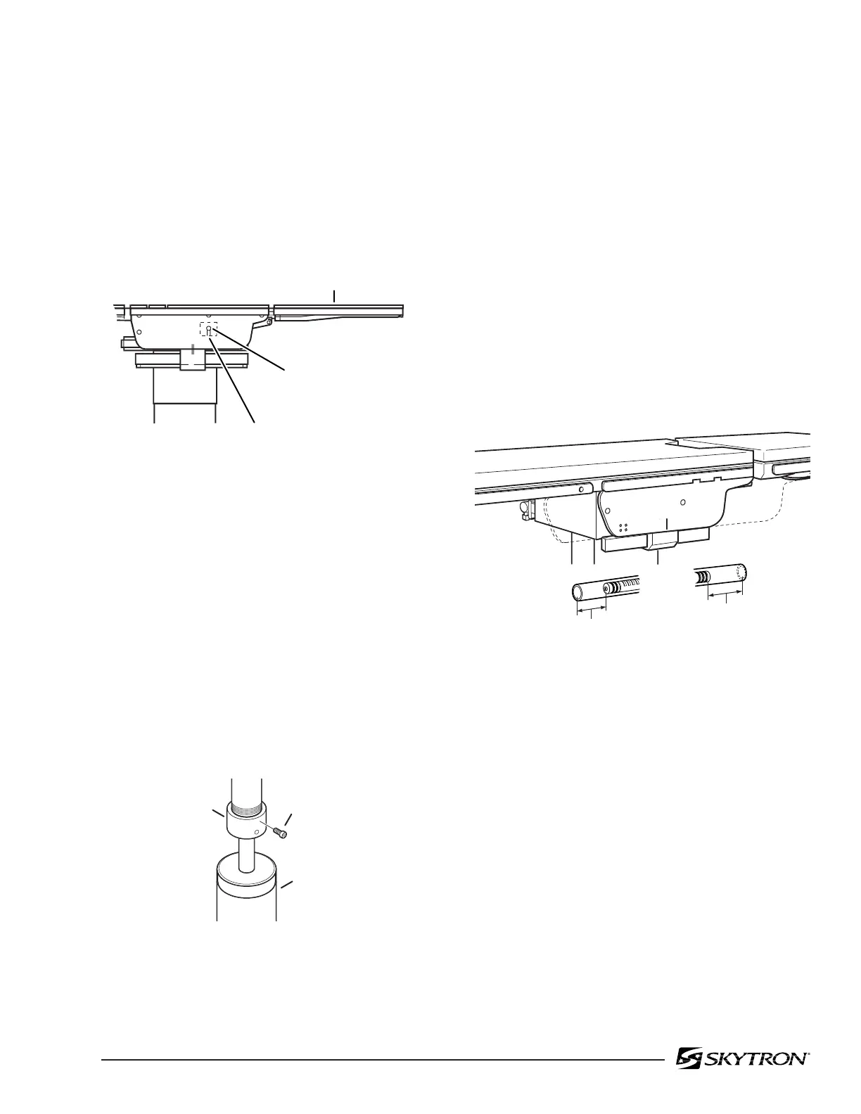
Loosen the cam locking set screws located inside
the table side frames. See figure 2-3. Use an allen
wrench to turn the cylinder eccentric cams as
required to shift either cylinder fore or aft as needed
so no twisting or flexing of the leg section is
observed when it is stalled in the above horizontal
position. Tighten set screws when proper adjust-
ment is achieved.
Figure 2-3. Leg Section Adjustment
c. Trendelenburg Cylinder Ball Joint
Inspect the Trendelenburg ball joint on a periodic
basis. Check for play of table top by sliding the table
top to each extremity and applying a load. Observe
for any movement in the joint. No visible play is
permitted. If movement is observed inspect the
tightness of the ball joint collar and the locking allen
bolt. See figure 2-4. Also inspect the ball socket for
signs of wear or metal particulate. Lubricate peri-
odically using a white lithium based grease.
d. Slide and Kidney Lift Cylinders
If the Slide or Kidney Lift cylinder has been re-
moved, the distance from the end of the piston to
the end of the cylinder housing must be checked to
make sure the functions will operate correctly.
With table top centered, the distance from the
end of the Slide piston to end of cylinder is:
Head End - 82 mm Foot End - 120 mm
The table top should slide 7-1/2" toward the head
and 13-1/4" toward the foot when positioned prop-
erly. Refer to figure 2-5.
With Kidney Lift all the way down, the distance
from the end of the Kidney Lift piston to end of
cylinder is:
Head End - 82 mm Tail End - 11 mm
LEG SECTION
SET SCREW
LEG SECTION
CYLINDER
ECCENTRIC CAM
82206-203
82mm
120mm
7-1/2"
SLIDE
TOWARD
HEAD
13-1/4"
SLIDE
TOWARD
FOOT
82206-204
Figure 2-4. Trendelenburg Cylinder
Figure 2-5.
2-3. Head Section Adjustment
The head section can be adjusted to eliminate any
flexing throughout it's range of travel.
To adjust:
Place the head section in level position and remove
the top. See figure 2-6. Loosen but do not remove
the allen bolts securing the bearing block to the
frame. Loosen the allen bolt in the top of the frame
and turn the set screw as required to achieve
proper adjustment. One or both of the blocks may
require adjustment to achieve proper alignment.
Tighten all allen bolts when adjustment is com-
plete. Test the head section throughout its range of
travel. Re-adjust as needed. Replace top section
when proper adjustment is achieved.
ALLEN BOLT
TRENDELENBURG
CYLINDER
BALL JOINT
COLLAR
82106-101

 Loading...


