Page 13
When activated, the return hydraulic circuit oper-
ates similar to the elevation cylinder return circuit.
Return springs inside the single action brake cylin-
ders retract the brake pads and provide the pres-
sure to return the hydraulic oil back to the reservoir.
The electronic timer operates the return circuit for
approximately 8-10 seconds.
g. Emergency Brake Release
The emergency brake release is simply a manually
operated bypass valve connected in parallel to the
brake cylinders and the oil reservoir. See figure 1-
16. When the valve is opened (turned counter-
clockwise) a return circuit for the brake hydraulic
fluid is opened. The return springs force the pistons
up pushing the hydraulic oil back into the reservoir
and retracting the brake pads.
Figure 1-16.
NOTE
•The emergency brake release valve
must be tightened securely when not in
use.
•If the emergency brake release valve
has been operated, the UNLOCK but-
ton on the pendant control may have to
be pressed before brakes will lock again.
If the emergency brake release valve is open, the
brakes will release slowly- depending on how far
open the valve is, this could take anywhere from a
few minutes to several hours.
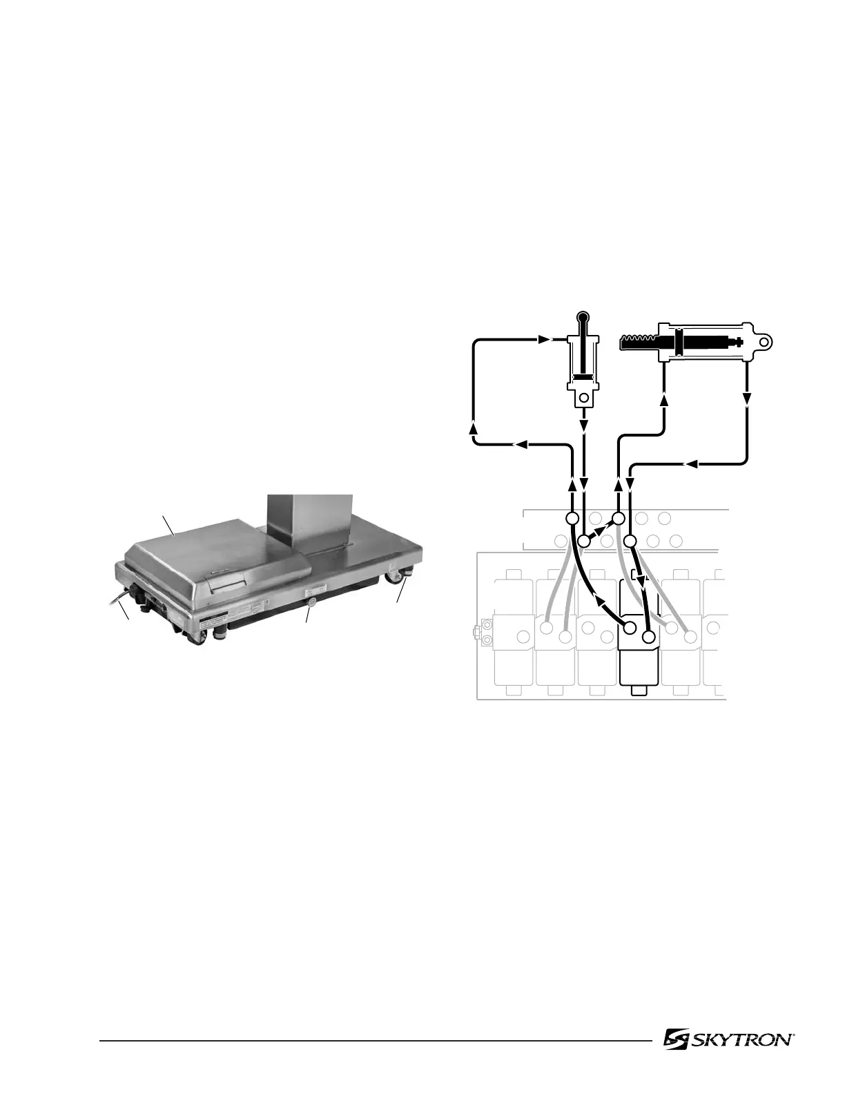
h. Flex/Reflex System
The Flex/Reflex system incorporates an additional
mini-valve which connects the Trendelenburg and
back section hydraulic systems in a series. When
FLEX is activated by the pendant control, the Flex/
Reflex mini-valve opens the oil pressure path to the
Reverse Trendelenburg piston. The return oil path
from the Trendelenburg piston is routed through
the back section cylinder to the mini-valve return
port. See figure 1-17
Figure 1-17. Flex/Reflex System
SERVICE ACCESS
COVER
POWER
CORD
EMERGENCY
BRAKE RELEASE
BRAKE (4)
82206-116
FLEX/
REFLEX
2
7
3 7
PLUMBING
TERMINAL
2
TREND.
7
BACK
UP
MINI-
VALVES
6
BACK
DOWN
2 6
3
REV.
TREND.
82206-117

 Loading...


