Page 14
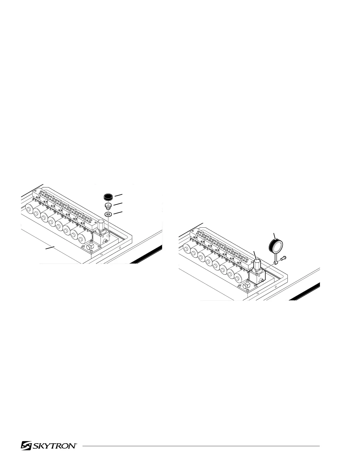
Figure 1-19.
2. Raise the table top until the piston reaches
the end of its stroke and stalls. Observe reading
on pressure gauge and turn the adjustment nut
(clockwise to increase oil pressure, counterclock-
wise to decrease) until desired reading is obtained.
Pressure should be 8MPA (80KG/CM
2
-1138 PSI).
An erratic reading and/or inability to adjust to the
recommended setting may indicate the need for
replacement of the pressure relief valve.
1-3. Hydraulic Adjustments
a. Fluid Level.
The fluid level should be approximately 1/2" below
the filler hole or gasket surface. If additional fluid is
needed, remove the filler vent cap with a phillips
screwdriver and add fluid through this opening
using a funnel. See figure 1-18.
NOTE
The elevation cylinder should be com-
pletely down, the brakes released and
all the other control functions in their
neutral position when checking oil level.
NOTE
Whenever a hydraulic line or compo-
nent is replaced, bleed the air out of the
lines using the pump pressure by acti-
vating the function before making the
final connection. Then operate the func-
tion until it stalls in both directions.
c. Pressure Relief Valve
The pressure relief valve is adjusted by turning the
adjustment nut until the desired pressure is reached.
To adjust:
1. Remove the plumbing bolt securing the
brake system line to the pressure relief valve and
attach a hydraulic pressure gauge to the main oil
galley using a long 6mm plumbing bolt. See figure
1-19.
Figure 1-18.
The type of oil that should be used is Mobil DTE #25
or equivalent. This is a very high quality hydraulic
oil. The table requires approximately two quarts of
oil to operate properly. Excercise caution when
determining equivalance to avoid damage to the
hydraulic system.
b. Bleeding The Hydraulic System
To purge the air from the hydraulic system, operate
each function back and forth at least two or three
times.
82206-118
FILLER CAP
FITTING
GASKET
OIL TANK
RESERVOIR
82206-119
PRESSURE
RELIEF
VALVE
PRESSURE
GAUGE
PLUMBING
BOLT

 Loading...


