Page 42
Figure 5-15.
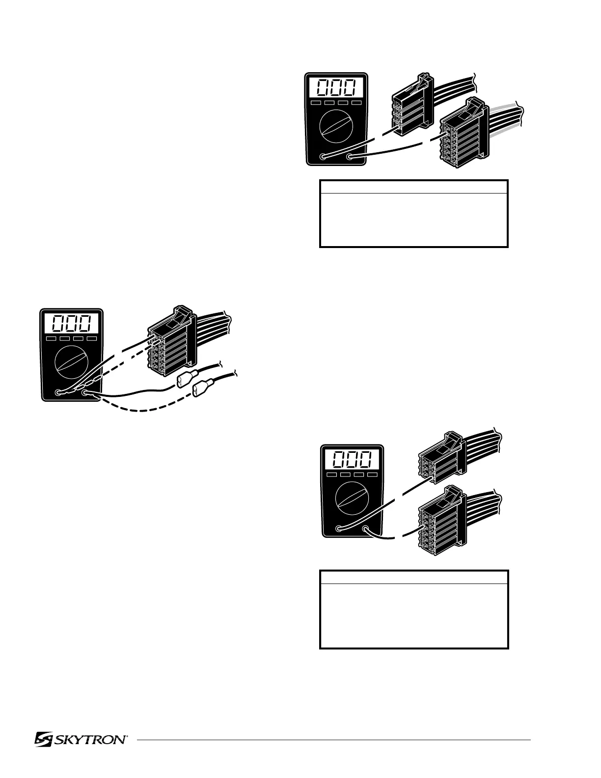
c. CN4 to Capacitor / Rectifier Unit Test
1. Disconnect connectors CN4, and HN3.
Leave all other connectors connected.
2. Using an ohmmeter, test for continuity
between pins of CN4, and HN3. See figure 5-16.
Figure 5-16. CN4 and HN3
HN4
CN4
1
3
WIRE COLOR / PIN NUMBER CODES
HN4 CN4
3
4
7
8
RED
BLACK
WHITE
WHITE
1
2
3
4
82306-514
PIN TEST COMBINATIONS
HN3 CN4
5
6
9
10
11
-
-
-
-
-
1
2
3
4
5
82306-515
CN4HN3
1
5
Figure 5-14.
NOTE
The 15 amp battery protection circuit
breaker is in the line between CN4 pin
1 and the battery connector. Test the
continuity of the circuit breaker if cor-
rect meter reading is not received.
b. CN4 to Pump Test
1. Disconnect connectors CN4 and HN4. Leave
all other connectors connected.
2. Using an ohmmeter, test for continuity
between the pins of CN4 and pins on HN4. See
figure 5-15.
82306-513
CN4
(+) RED
(-) BLUE
1
2
5-9. Main Wire Harness Continuity Tests
If correct meter readings are not received in tests
between components, before replacing the com-
ponents, test the Main Wire Harness to be sure all
connectors and wires are making a good connec-
tion.
a. CN4 to Batteries Test
1. Disconnect connectors CN4 and the (+) and
(-) connectors from the batteries. Leave all other
connectors connected.
2. Using an ohmmeter, test for continuity
between pin 1 of CN4 and battery (+) connector.
Also test between pin 2 of CN4 and battery (-)
connector. See figure 5-14.

 Loading...


