Page 41
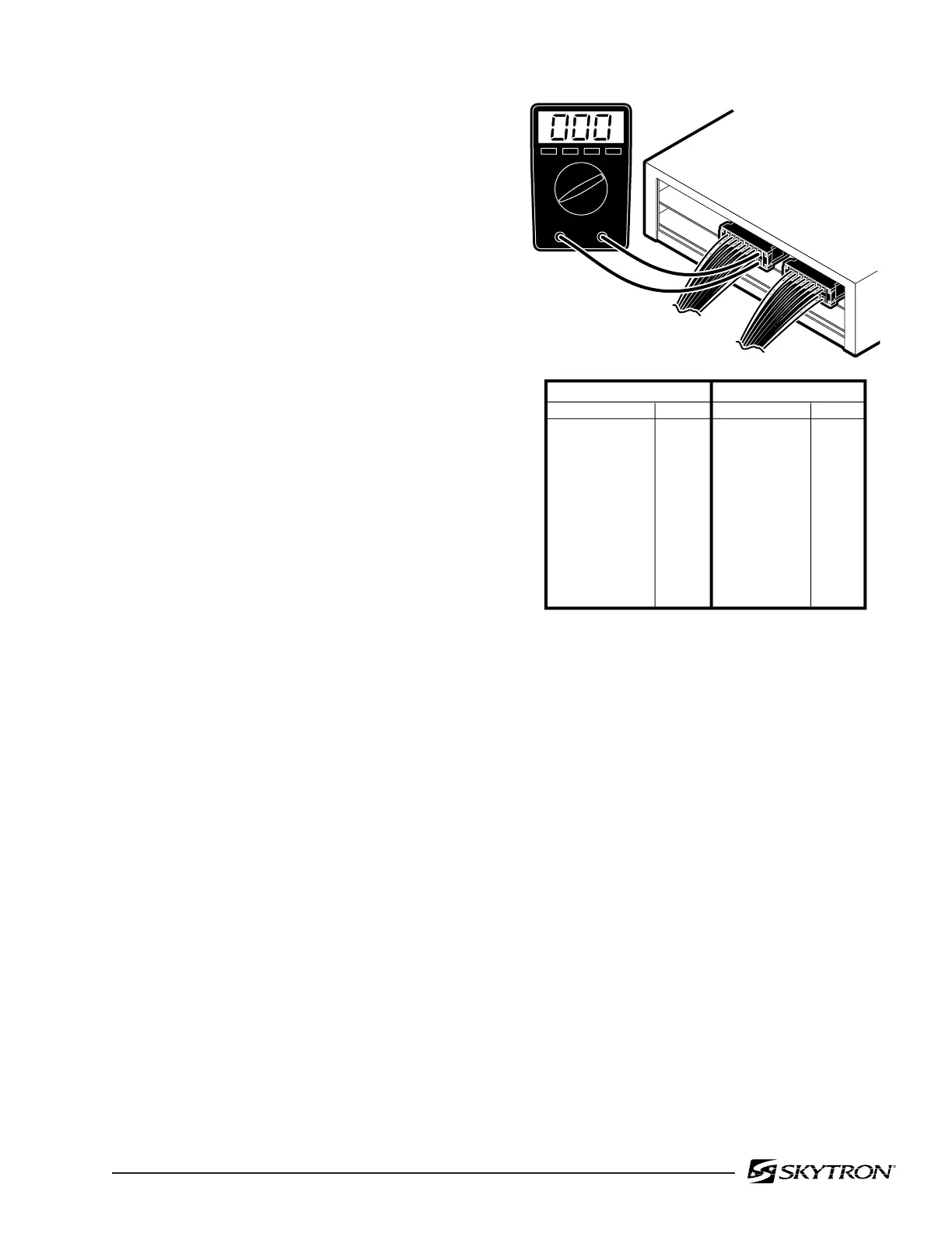
Figure 5-13. Solenoid Output Connectors
NOTE
•Before deciding the relay box is de-
fective, check the wires and pins in the
connector blocks to make sure they
are not loose or making a bad connec-
tion with their mate.
•If the battery power is ON and no table
functions have been activated for 3
hours, the power off circuit will interrupt
the battery power.
f. Checking Output to Pendant Control
The output to the Pendant Control can not be
tested without specialized equipment. If all tests
have been conducted and it appears that the Relay
Box is faulty, contact SKYTRON.
d. Checking Output to Solenoids
This test checks the voltage that is used to
energize the solenoids.
1. Activate either BATTERY or AC120V oper-
ating mode.
NOTE
•The Brake Lock function is activated
by pressing any function button (except
BRAKE UNLOCK). A timer in the Relay
Box allows continuous output for about
7 seconds. If the brakes are already
locked, no output is provided.
•The BRAKE UNLOCK button activates
another timer in the relay box which
allows continuous output for the brake
release function for approximately 7
seconds. If the brakes are already
released (using the BRAKE UNLOCK
button) no output is provided.
2. Test connectors CN1A and CN1B from the
back while attached to the relay box. All connec-
tors should be connected.
3. Activate each of the pendant control buttons
and measure the output voltage for the corre-
sponding connector pins with a DC voltmeter. See
figure 5-13. Meter should read 24 volts.
e. Test Results:
If you do not receive the correct meter readings, the
relay box is defective and should be replaced.
82306-512
CN1A
CN1B
CN1A CONNECTOR
FUNCTION
PINS
Table Up
Table Down
Trendelenburg
Re. Trendelenburg
Tilt Right
Tilt Left
Reflex
Flex
1 - 2
3 - 4
5 - 6
7 - 8
9 - 10
11 - 12
13 - 14
15 - 16
CN1B CONNECTOR
FUNCTION PINS
Back Up
Back Down
Slide To Foot
Slide To Head
Kidney Down
Kidney Up
Leg Up
Leg Down
Brake Set
Brake Unlock
1 - 2
3 - 4
5 - 6
7 - 8
9 - 10
11 - 12
13 - 14
15 - 16
17 - 18
19 - 20

 Loading...


