Page 12
3. Manually controlled emergency brake re-
lease.
4. Plumbing terminal, flexible hoses, copper
lines and "O" rings.
5. Portions of the electrical system.
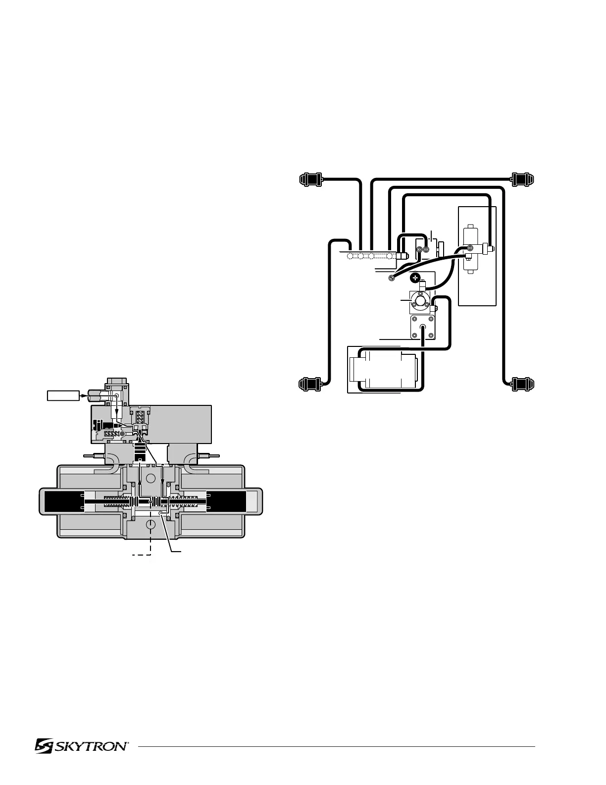
Figure 1-15. Brake System Block Diagram
Each corner of the cast-iron table base has a
hydraulic brake cylinder. These single action cyl-
inders are hydraulically connected in parallel to the
mini-valve and all four are activated together. It is
normal for one corner of the table to raise before the
others due to the weight distribution of the table.
An electronic timer in the relay box is activated
when any function on the pendant control is
pushed momentarily. The pump/motor and brake
system mini-valve are activated and the brake
cylinders are completely set. The electronic timer
runs for approx. 8-10 seconds.
The brakes are released by pushing the BRAKE
UNLOCK button momentarily. An electronic timer
in the relay box activates the brake function hy-
draulic mini-valve and pump/motor.
Figure 1-14. Elevation Return Circuit
f. Brake System
The brake system consists of the following compo-
nents: (figure 1-15)
1. Single action slave cylinders (4 each).
2. 3-way (single check valve type) mini-valve.
e. Elevation Cylinder Return Circuit
A three-way (single check valve type) mini-valve
controls both the elevation and return circuits. The
elevation circuit operation within the mini-valve is
identical to the operation of the four-way valves
previously described (inlet pressure opens the
check valve allowing the oil to enter the cylinder). In
the return position, inlet pressure pushes the pilot
plunger up and opens the return check valve. See
figure 1-14. The open check valve allows a path for
the oil in the elevation cylinder to return to the
reservoir. When the pilot plunger valve is opened,
the continuing pump pressure opens the pressure
relief valve which provides a return oil path to the
reservoir.
The mini-valve used in the elevation circuit con-
tains only one check valve (all four-way mini-valves
use two check valves). The check valve is used to
trap the oil in the elevation cylinder thereby sup-
porting the table top. When the top is being lowered
the check valve is mechanically held open by the
pilot plunger through pump pressure.
82206-114
TO RESERVOIR THROUGH
PRESSURE RELIEF VALVE
INLET
RETURN TO
RESERVOIR
EMERGENCY
BRAKE
RELEASE
82206-115
BRAKE
BRAKE
BRAKE
BRAKE
PLUMBING
TERMINAL
MOTOR/PUMP
ASSEMBLY
BRAKE
MINI
VALVE
PRESSURE
RELIEF
VALVE

 Loading...


