Page 29
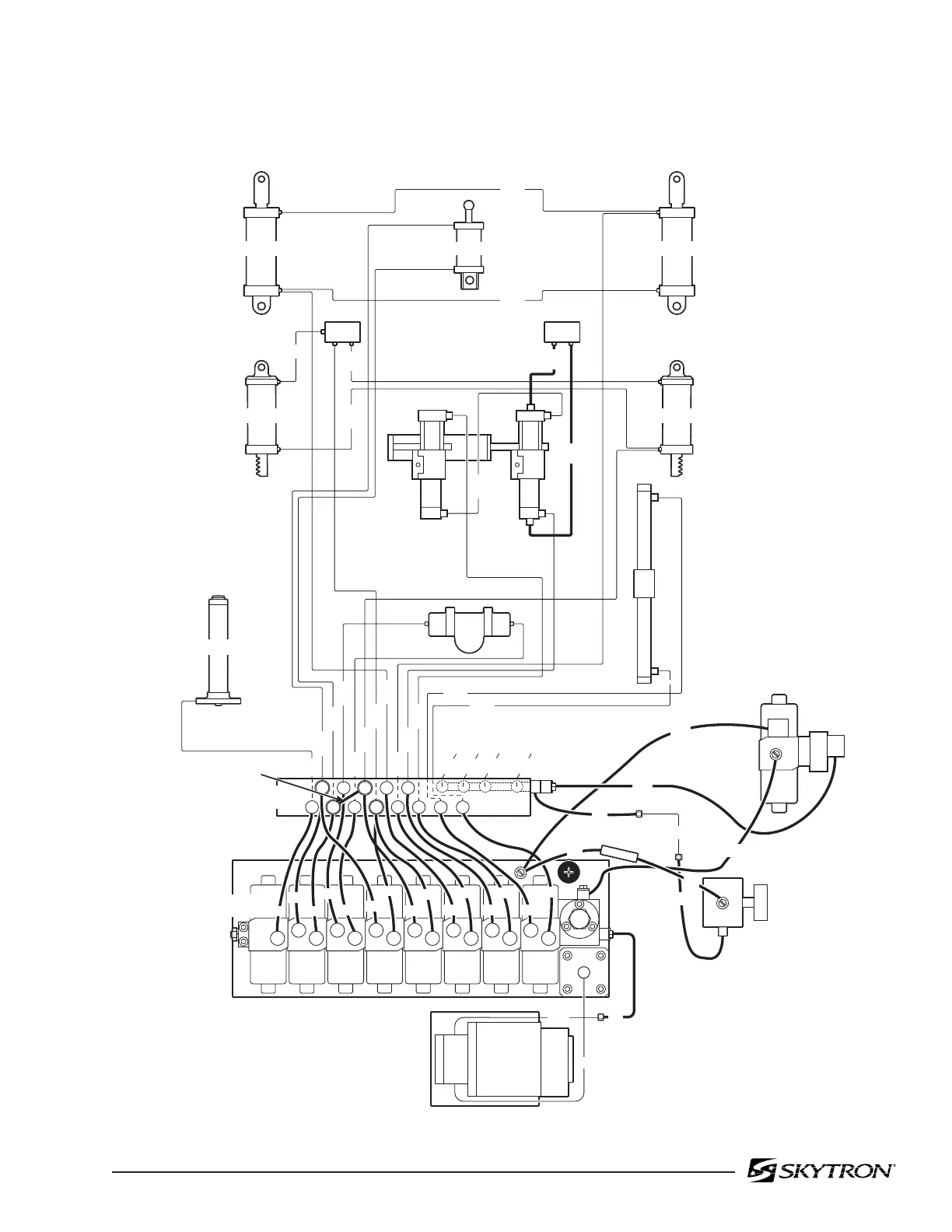
3-12. Flexible Hose Identification and Placement
The flexible hydraulic hoses used in the table are
number coded to aid in the correct placement of the
Figure 3-10. Flexible Hoses
hoses from the plumbing terminal to their respec-
tive hydraulic cylinders. Figure 3-10 shows the
correct placement of the flexible hydraulic hoses
and their respective number codes.
MOTOR/ PUMP
ASSEMBLY
EMERGENCY
BRAKE
RELEASE
PLUMBING
TERMINAL
ELEVATION
1
240
600
L.F.
750
L.R.
670
R.R.
600
R.F.
TO BRAKE CYLINDERS
PRESSURE
RELIEF
VALVE
ASSEMBLY
MINI-
VALVES
1
3
2
4
5
7
6
9
8
10
11
13
2
7
1
5
2
4
9
7
6
3
105
140
115
140
130
140
150
135
120
100
100
135
100
120
BRAKE
MINI-VALVE
ASSEMBLY
400
11
KIDNEY
CYL.
LEFT
KIDNEY
CYL.
RIGHT
10
90
LEG SECTION
9
8
LEG SECTION
9
8
150
800
240
80
1900
2060
45
TILT
BACK SECTION
7
6
BACK SECTION
7
6
1200
2210
11
2600
2450
10
13
SLIDE
CYLINDER
2170
2170
2400
2500
1150
1000
2300
8
1470
1370
2
3
TRENDELENBURG
COMPENSATING
VALVE
1270
12
130
12
14
360
300
40
40
80
14
31.6
280
DC
PUMP
230
80
240
82506-310
12
13

 Loading...


