Page 39
5-7. Auxiliary Switches
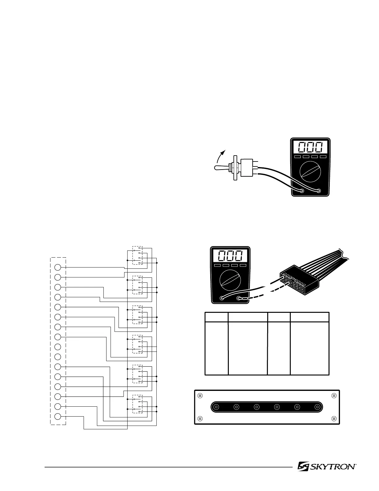
The following tests will determine if the auxiliary
switches are functioning properly.
a. Switch Test
Disconnect connector CN2 at the Relay Box and
using an ohmmeter check for continuity at the
connector pins (pin 1A common) while activating
the appropriate switch. See figure 5-9. Meter
should read 0 ohms.
Figure 5-9. Auxiliary Switch Connector CN2
Figure 5-10. Auxiliary Switch Test
82306-509
1
SW1
CN2
TABLE UP
TABLE DOWN
TREND
REV TREND
TILT RIGHT
TILT LEFT
BACK UP
BACK DOWN
KIDNEY DOWN
BRAKE LOCK
LEG UP
LEG DOWN
PUMP MOTOR
GROUND
SW2
SW3
SW4
SW5
SW6
2
3
4
5
6
7
8
9
10
11
12
13
14
15
16
PIN NO
1 (A1)
2 (B1)
3 (A2)
4 (B2)
5 (A3)
6 (B3)
7 (A4)
8 (B4)
Red
Green / White
Brown
Yellow
Orange
Green
Brown / White
Blue
9 (A5)
10 (B5)
11 (A6)
12 (B6)
13 (A7)
14 (B7)
15 (A8)
16 (B8)
--
--
Black
Blue / White
Gray
Yellow / White
Red / White
Orange / White
COLOR
PIN NO
COLOR
CN2
B8/B2 B8/A3
B8/A4
B8/A1 B8/A7 B8/B6
B8/A2 B8/B3 B8/B4 B8/B1 B8/B7 B8/A6
REV
TREND
TILT
RIGHT
BACK
UP
TABLE
UP
LEG
UP
BRAKE
LOCK
TREND
TILT
LEFT
BACK
DOWN
TABLE
DOWN
LEG
DOWN
KIDNEY
DOWN
1(A1)
6(B3)
b. Test Results
If proper meter readings are not received, test the
individual switches as necessary. Using an ohmme-
ter, test the operation of an individual switch with the
(+) test lead at the center terminal of the switch and
the (-) test lead at the terminal opposite the direction
of the switch actuation. Refer to figure 5-10. Meter
should read 0 ohms. If the switches check out, the
problem would have to be in the wires, the switch
circuit board or connector CN2.

 Loading...


