Page 38
a. Pendant Control Test
There are some serviceable components within
the Pendant Control. The cord is detachable and
can be tested for continuity between the pins on the
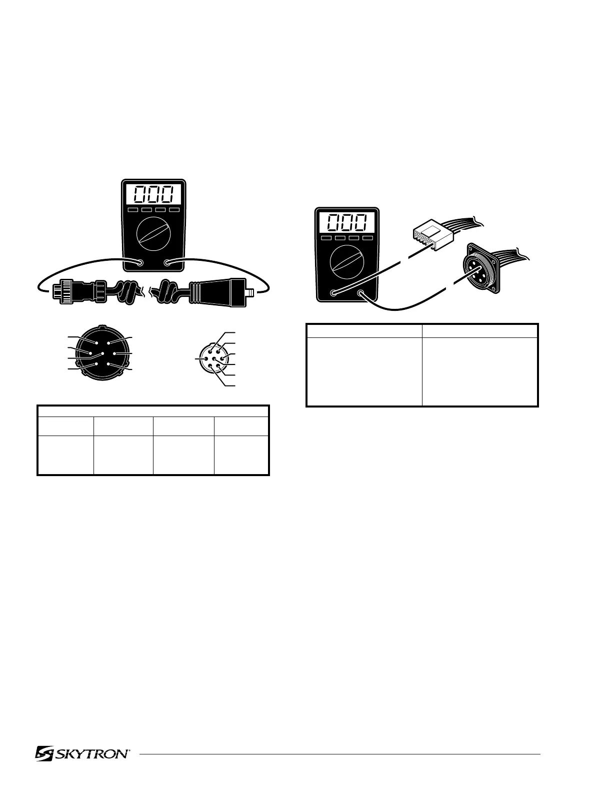
connectors. Use the following procedure to test the
pendant control cord. See figure 5-7.
Figure 5-7. Pendant Control Test
Disconnect the cord from the table connector and
from the pendant control connector and using an
ohmmeter, test the continuity between the corre-
sponding pins in the connectors.
b. Test Results
If you do not receive the correct readings, the
wiring or connector pins may be faulty.
Figure 5-8. Table Connector Continuity Test
d. Test Results
If the correct readings are not obtained, test the
wiring from the table connector HN8 to connector
HN7 (located behind the Pendant Connector Hous-
ing) and from connector CN7 to HN7. Disconnect
connector HN7 and using an ohmmeter, test the
continuity between the corresponding pins in con-
nectors HN7 to CN7 and HN7 to HN8. Refer to
figure 5-8.
If the correct readings are obtained, this part of
the circuit is okay and the problem may be the
Pendant Control or the Relay Box. Contact
SKYTRON if all tests performed indicate that the
problem is located in the Pendant Control.
c. Table Connector HN8 Test
If correct readings are received, test the wiring from
the table connector to connector CN7 at the Relay
Box. Disconnect connector CN7 from the Relay
Box and using an ohmmeter, test the continuity
between the corresponding pins in connectors
CN7 and the table connector HN8. See figure 5-8.
82306-507
Test Leads
Base Conn.
Pin
1
2
3
4
1
6
2
7
5
6
7
5
4
3
Pend. Conn.
Pin
Base Conn.
Pin
Pend. Conn.
Pin
BLACK 1
GREEN 4
RED 3
WHITE 6
2 BROWN
5 BLUE
7 YELLOW
1 BLACK
3 RED
4 GREEN
7 YELLOW
2 BROWN
6 WHITE
BLUE 5
BASE END PENDANT END
82306-508
CN7
HN8
1
1
LT. GREEN/WHITE
CN7 CONNECTOR HN8 CONNECTOR
1
2
3
4
5
6
7
1
2
3
4
5
6
7
LT. GREEN / WHITE
LT. GREEN
GREEN / BLACK
GREEN / RED
GRAY
GRAY / WHITE
- - -

 Loading...


