Page 23
3-6. FLEX SYSTEM DIAGNOSIS CHART
Reason
Incorrect Speed Adjustment (Trendelenburg, Back
section or Flex - check with gauge)
Spool Valve Not Centered
Defective Check Valves
Low on Oil
Pinched Hose
Defective Mini-Valve
Pressure Relief Valve Not Set Properly
Defective Solenoid
Defective Relay Box or Pendant Control
Kidney Bridge Raised
Worn Ball Joint or Retainer Nut
Defective or Dirty Check Valves
Oil Leakage in Circuit
Air Inside Cylinder
Pinched Hose
Low on Oil
Problem
Back Section or Trendelenburg function moves
improperly
NOTE
If Flex System does not function prop-
erly, check the back section and
Trendelenburg functions before ad-
justing the flex system.
Back Section or Trendelenburg function chatters
or loses position
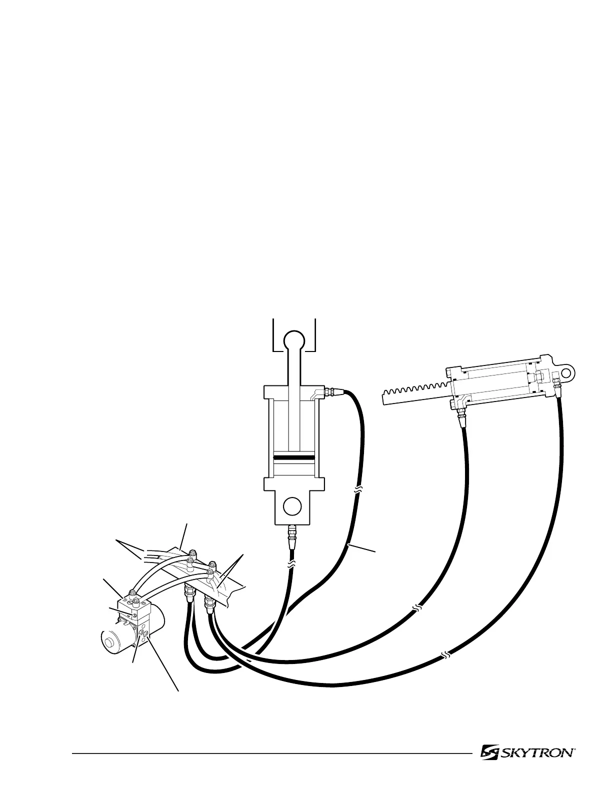
Figure 3-4. Flex System Circuit
82206-304
TO TRENDELENBURG
MINI-VALVE
TO BACK SECTION
MINI-VALVE
SPEED
CONTROL
CHECK
VALVE
PLUMBING
TERMINAL
TRENDELENBURG
CIRCUIT
BACK SECTION CIRCUIT
MINI-VALVE
INTERNAL OIL RETURN TO RESERVOIR
INTERNAL
OIL FROM PUMP
FLEXIBLE
HOSE

 Loading...


