Page 30
3-13. Kidney Lift System
The Kidney Lift cylinders are connected in series so
that both cylinders operate simultaneously.
Hydraulic pressure on one side of the lead piston
causes the piston to move. The piston movement
forces the hydraulic fluid on the other side of the
piston through the system to the other cylinder.
This simultaneously activates the other piston. A
bypass valve is connected to the right cylinder
assembly for initial setup and adjustment of the
kidney lift system. Refer to figure 3-9 for valve
location. Use the following procedures to bleed or
adjust the system if needed.
a. Bleeding the System
If the hydraulic lines or cylinders have been discon-
nected from the kidney lift system for any reason,
use the following procedure to bleed the air from
the system.
1. Remove the kidney lift top section and begin
the procedure with both pistons in the down posi-
tion (chambers A & C) as shown in figure 3-11.
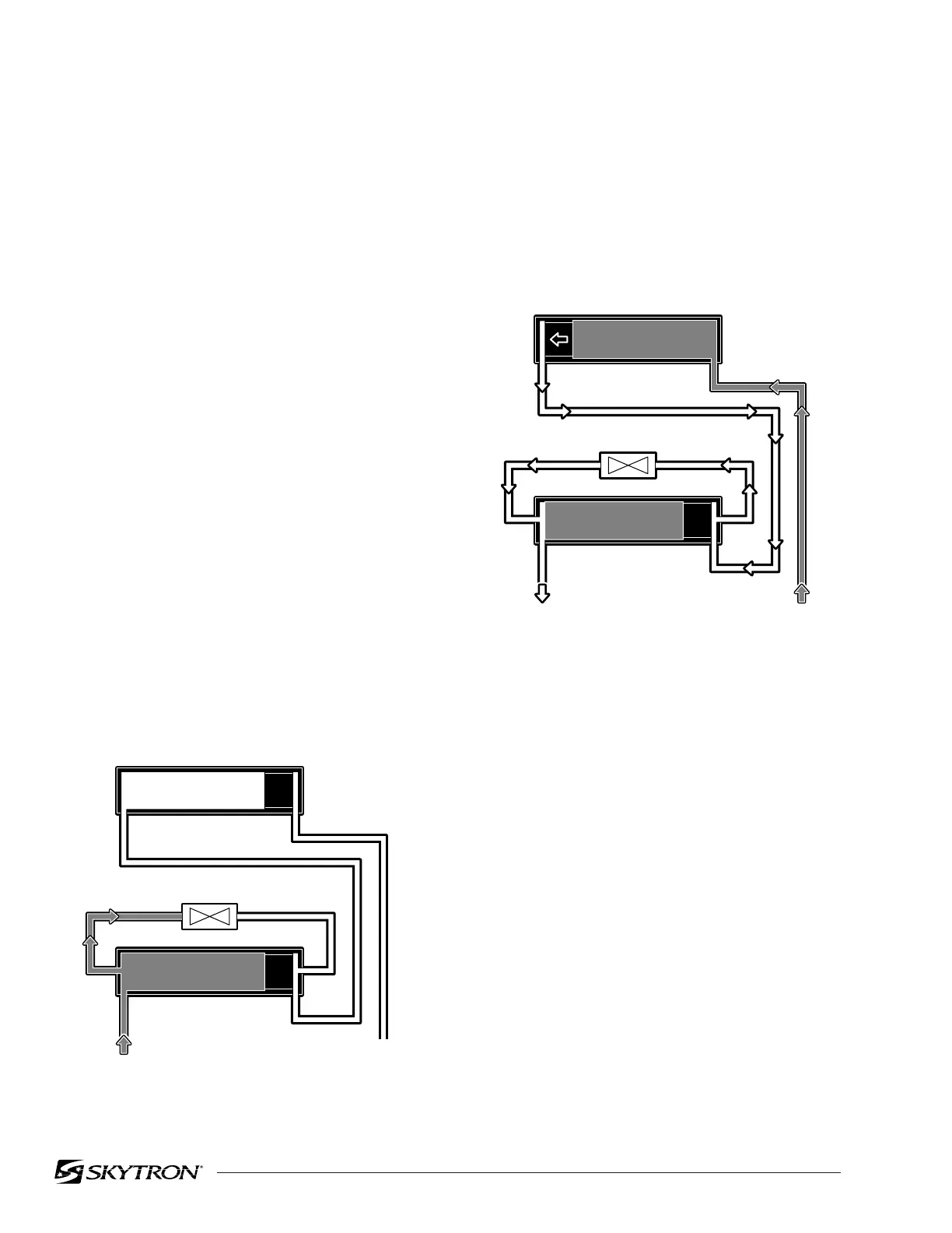
2. Make sure the bypass valve is closed (valve
screw tight) and activate "KIDNEY DOWN". The
hydraulic fluid will fill cavity "D" as shown in figure
3-11.
Figure 3-11.
Figure 3-12.
3. Open the bypass valve by loosening the
screw in the bottom of the valve and activate
"KIDNEY UP". Hydraulic fluid fills cavity "A" and
pushes the piston into cavity "B". The open valve
allows a path for air to escape from cavity "B"
without affecting the piston in "C". See figure 3-12.
82206-311
LEFT CYLINDER
RIGHT CYLINDER
DC
BA
BYPASS VALVE (closed)
KIDNEY LIFT
DOWN
82206-312
LEFT CYLINDER
RIGHT CYLINDER
DC
BA
BYPASS VALVE (open)
KIDNEY LIFT
UP

 Loading...


