Page 47
a. Switch Test
Turn Main Power ON, lock the table brakes, and
place the table top sections in a level position with
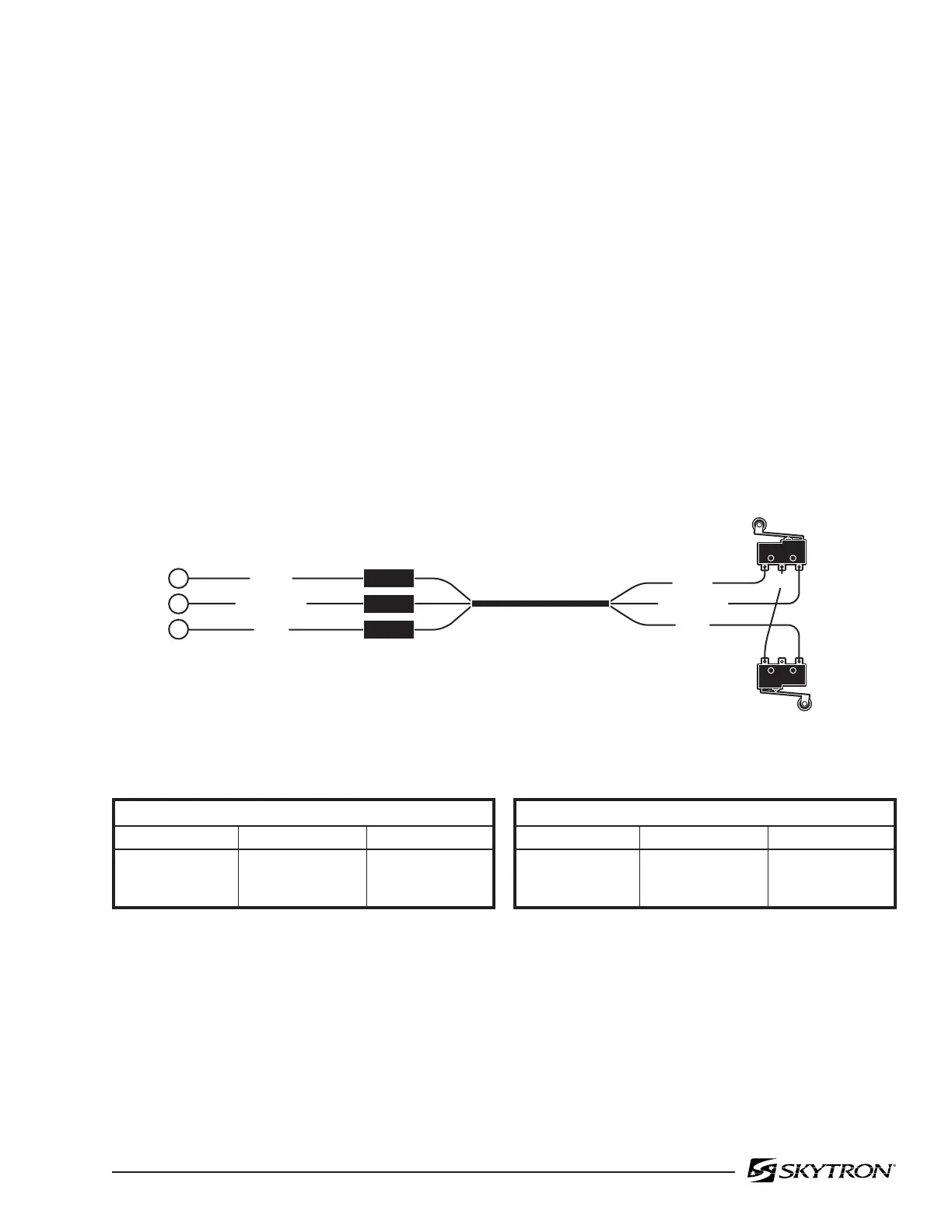
the Kidney Lift down. Disconnect connector CN10
from the relay box and using an ohmmeter, test the
wiring and switch operation at the appropriate pin
numbers for the micro-switch in question as shown
in figures 5-23 through 5-30.
NOTE
Be sure to isolate the circuit when mak-
ing continuity checks.
NOTE
If you do not receive the proper continu-
ity results at connector CN10 it does not
necessarily mean the micro-switch is
defective. There could be a problem
with the riser cord between connector
CN10 and terminal strips TM1 and
TM2, or in the wiring from the switch to
connector. Further tests will have to be
made to determine the exact problem.
Figure 5-23. Trendelenburg Return Switches
82306-522
NC
WHITE
LIGHT BLUE
BLUE
WHITE
LIGHT BLUE
BLUE
COM NCNO
COM
HEAD-DOWN TO LEVEL / TEST AT PINS 1 & 23
NS-1 TRENDELENBURG
Table Position
Level
Head-Up
Head-Down
Switch Position
Open
Open
Closed
Meter Reading
Infinity
Infinity
0
HEAD-UP TO LEVEL / TEST AT PINS 2 & 23
NS-2 REVERSE TRENDELENBURG
When table is in Trendelenburg Position,
NS-1 brings the top back to level.
When table is in Reverse Trendelenburg Position,
NS-2 brings the top back to level.
Table Position
Level
Head-Up
Head-Down
Switch Position
Open
Closed
Open
Meter Reading
Infinity
0
Infinity
NS-1
NS-2
(CN10)
NO
TM1-1
TM1-5
TM1-2
1
23
2

 Loading...


