IDP 600 Terminal Series - Hardware Guide
T200, Version 02 14 © SkyWave Proprietary
3.3.2 Digital Output
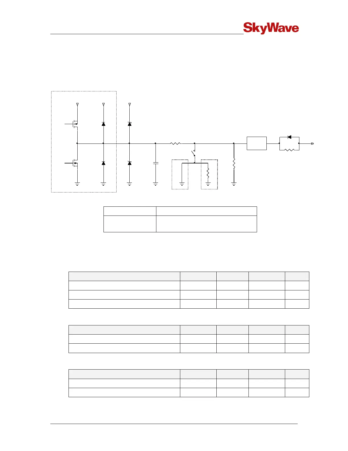
Figure 13 shows a schematic of the I/O when configured as a digital output. It must be
noted that I/O 04 is the only I/O with built-in short circuit protection for open drain
outputs.
Figure 13 Digital Output
S1 = Closed (Low Impedance)
S1 = Open (High Impedance)
The following tables describe the output specifications.
Push-pull
In the push-pull configuration the output is driven directly from the microprocessor.
Output high voltage - open circuit
Output high voltage (sourcing 25 µA)
Output low voltage (sinking 25 µA)
Open Drain (I/O 01 to I/O 03)
Sink current (do not exceed)
Voltage (active drawing at 250 mA)
Protected Open Drain (I/O 04 only)
Sink current (current limited)
I/O4
2R
S1
I/O1
1M
1k
3V
1nF
3V 3V
ARM PROCESSOR
OUTPUT
DIGITAL
I/O2
I/O3
1k
3V
LIMITER