IDP 600 Terminal Series - Hardware Guide
T200, Version 02 38 © SkyWave Proprietary
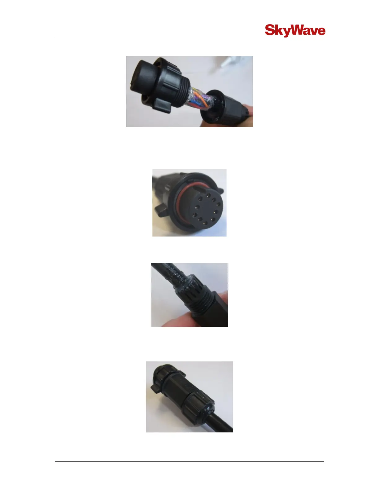
Figure 38 Silicone in the Grommet
10. Assemble the back shell to the connector body and wipe away any excess sealant
(Figure 39). To aid in tightening the back shell, align the coupling ring key feature
with the slot in the connector body (Figure 39).
Figure 39 Key Features in the Coupling Ring and Connector Body
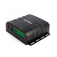
11. Apply sealant over the cable exit area as shown in Figure 40.
Figure 40 Cable Exit Area
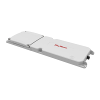
12. Assemble the sealing nut over the back shell until the cable grip makes full contact
with the perimeter of the cable jacket (Figure 41). Wipe away any excess sealant.
Figure 41 Assembled Sealing Nut