IDP 600 Terminal Series - Hardware Guide
© SkyWave Proprietary v T200, Version 02
List of Figures
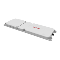
Figure 1 IDP-680 Model ............................................................................................................ 1
Figure 2 SkyWave's IsatData Pro Network ............................................................................... 2
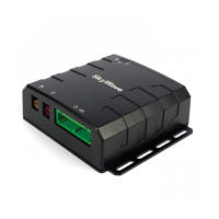
Figure 3 IDP-680 with Side Connector...................................................................................... 3
Figure 4 IDP-680 with Bottom Connector ................................................................................. 3
Figure 5 IDP-690 with Side Connector...................................................................................... 4
Figure 6 IDP-690 with Bottom Connector ................................................................................. 4
Figure 7 Pass-Through Mode ..................................................................................................... 5
Figure 8 Terminal Connector Pin Assignment (Male) ............................................................... 9
Figure 9 View of Terminal Male Connector ............................................................................ 10
Figure 10 Face View of Mating Connector (Female) ................................................................ 10
Figure 11 Rear View of Mating Connector (Solder Cups) ........................................................ 10
Figure 12 Digital Input............................................................................................................... 13
Figure 13 Digital Output ............................................................................................................ 14
Figure 14 Analog Input .............................................................................................................. 15
Figure 15 Pass-Through Mode Signals ...................................................................................... 16
Figure 16 IDP-680 Top View Enclosure Dimensions (mm) ..................................................... 19
Figure 17 IDP-680 Side View Enclosure Dimensions (mm) ..................................................... 19
Figure 18 IDP-680 and IDP-690 Bottom View Enclosure Dimensions (mm) .......................... 19
Figure 19 IDP-690 Side View Enclosure Dimensions (mm) ..................................................... 20
Figure 20 Mobile ID Location ................................................................................................... 24
Figure 21 Sample Activation Report ......................................................................................... 25
Figure 22 Sample Cable Placement in a Vehicle Cab ............................................................... 28
Figure 23 Bottom Connector and Side Connector (IDP-680 shown) ........................................ 29
Figure 24 Location for Waterproof Sealing Compound ............................................................ 30
Figure 25 Apply Silicone Lubricant to Connector ..................................................................... 30
Figure 26 Key Slot ..................................................................................................................... 31
Figure 27 Cable Connector and Locking Collar ........................................................................ 31
Figure 28 Cable Management .................................................................................................... 32
Figure 29 LED Location ............................................................................................................ 33
Figure 30 Basic Connector Parts for Soldering Configuration .................................................. 35
Figure 31 Recommended Stripping Length ............................................................................... 35
Figure 32 Cable with Sealing Nut, Back Shell and Coupling Ring ........................................... 36
Figure 33 Cable Grommet ......................................................................................................... 36
Figure 34 Red Gasket................................................................................................................. 36
Figure 35 Wires and Solder Cups .............................................................................................. 37
Figure 36 O-Ring over Connector Body .................................................................................... 37
Figure 37 Silicone in the Connector .......................................................................................... 37
Figure 38 Silicone in the Grommet ............................................................................................ 38
Figure 39 Key Features in the Coupling Ring and Connector Body ......................................... 38
Figure 40 Cable Exit Area ......................................................................................................... 38
Figure 41 Assembled Sealing Nut ............................................................................................. 38
Figure 42 IDP 600 Series Mating Cable .................................................................................... 43
Figure 43 Face View of IDP 600 Series Mating Cable Connector ............................................ 44