IDP 600 Terminal Series - Hardware Guide
T200, Version 02 36 © SkyWave Proprietary
3. Twist the ends tightly to prevent stranded wires from fraying.
CAUTION Do not solder dip.
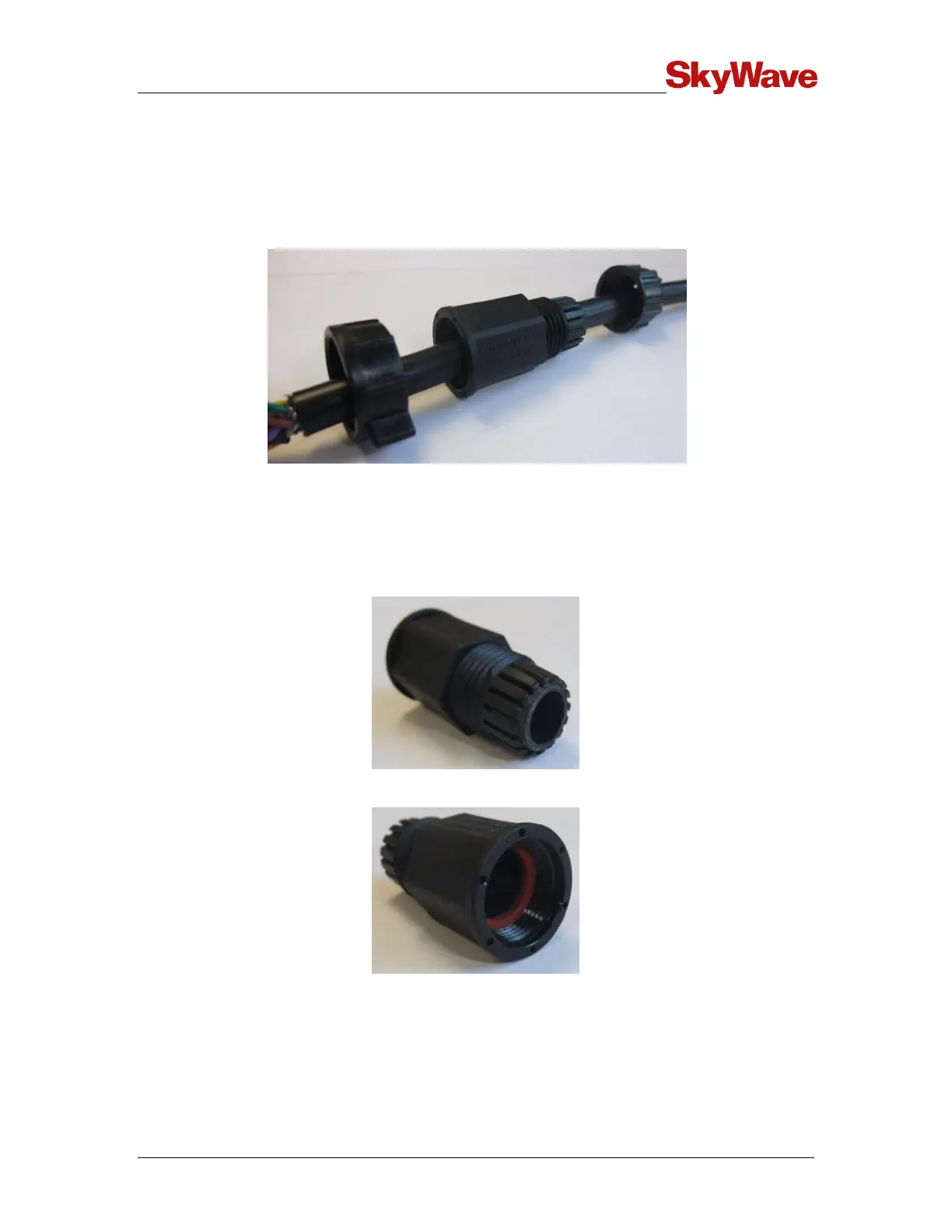
4. Slide the following items over the cable in sequence and as shown in Figure 32: a
sealing nut, a back shell and a coupling ring.
Figure 32 Cable with Sealing Nut, Back Shell and Coupling Ring
CAUTION Ensure that the black back shell cable grommet is present
inside the cable grip area (Figure 33) and the red gasket is
present and oriented with flat face visible as shown in
Figure 34.
Figure 33 Cable Grommet
Figure 34 Red Gasket
5. Using a soldering iron and solder, tin the wires and solder them to the connector
solder cups (Figure 35) as per the proper pin-out.