IDP 600 Terminal Series - Hardware Guide
T200, Version 02 16 © SkyWave Proprietary
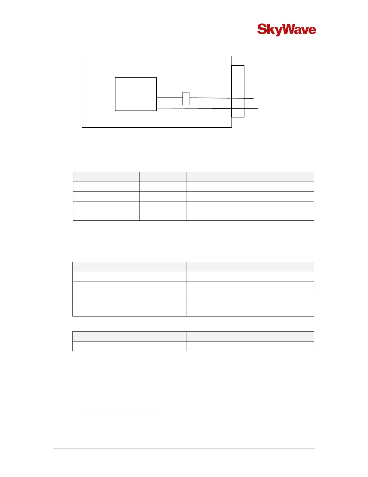
Figure 15 Pass-Through Mode Signals
The terminal's I/O lines are configured as per Table 6 when in pass-through mode. The
modem's serial data and the EVENT_NOTIFICATION pins are connected to the
terminal's external connector.
Table 6 Pass-Through Mode I/O States
Connected to EVENT_NOTIFICATION
Disabled if no valid RS-232 level on receiver
When in pass-through mode, the application controller samples inputs and drives the
equivalent output appropriately. Pass-through mode time specifications are given in
Table 7.
Table 7 Pass-Through Mode Timing Specifications
As per modem configuration
Maximum Jitter on Signals
(Modem to External)
Maximum Jitter on Signals
(External to Modem)
Table 8 Pass-Through Mode Power Consumption
Drawn from a 12 V supply. Average time of receive and idle current, with the DSP powered on
without any transmits or GPS receivers.