21
Using the Remote I/O:
Two 9-pin “D” type connectors are mounted on the rear panel that provides REMOTE-INPUT-OUTPUT control
and information.
These connectors mate with standard 9 pin D-sub-miniature connector provided by the user.
The output mates to a male (plug) connector while the input mates to a female (receptacle) connector.
For best performance, a shielded cable should be used. To avoid ground loops the shield should not
be grounded at both ends of the cable.
Suggested AMP part numbers for interconnecting to the Remote I/O
PLUG SHELL WITH GROUND INDENTS
CRIMP SNAP-IN PIN CONTACT (for plug)
CRIMP SNAP-IN SOCKET CONTACT (for receptacle)
SHIELDED CABLE CLAMP (for either plug or receptacle)
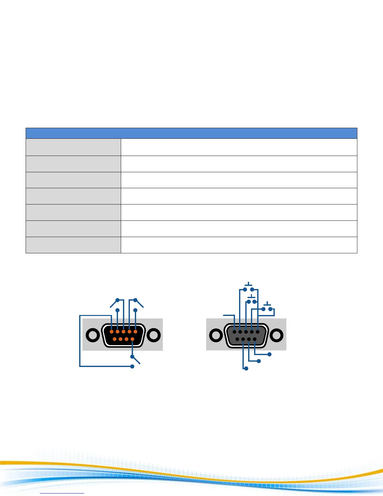
REMOTE I/O Pinouts:
FAIL
5
9
5
9
1
6
1
6
RESET
TEST
INTERLOCK
BIT 2
BIT 3
BIT 1
COMMON
PASS
PROCESSING