4
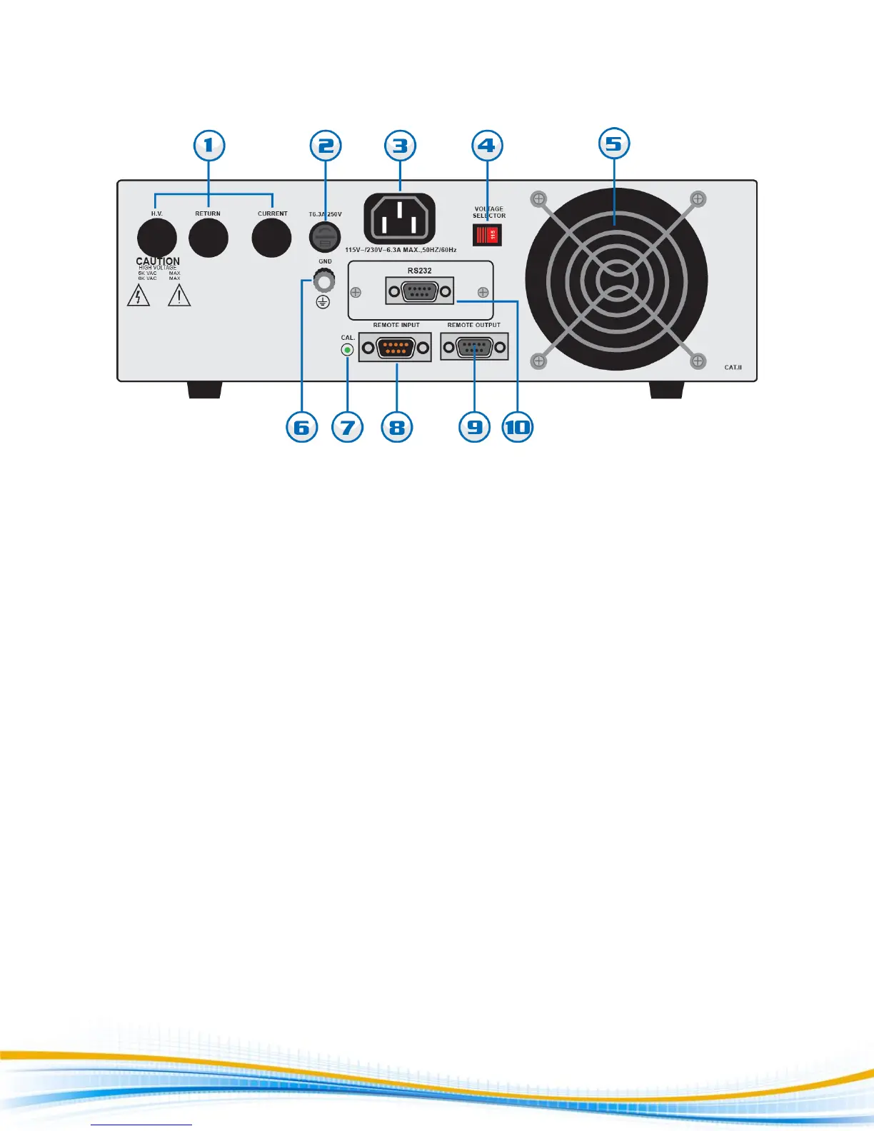
4320 Rear Panel Controls
1. POSITION FOR OPTIONAL REMOTE OUTPUT JACKS: Please refer section Optional Rear Panel Controls for
details.
2. FUSE RECEPTACLE: To change the fuse unplug the power (mains) cord and turn the fuse cap counter
clockwise to remove the fuse.
3. INPUT POWER RECEPTACLE: Standard IEC 320 connector for connection to a standard NEMA style line
power (mains) cord.
4. INPUT POWER SWITCH: Line voltage selection is set by the position of the switch. In the left position, it is
set for 115-volt operation, in the right position it is set for 230-volt operation.
5. THERMAL FAN: To cool the tester.
6. CHASSIS GROUND (EARTH) TERMINAL: This safety terminal should be connected to a good earth ground
before operation.
7. CALIBRATION ENABLE KEY: To enter the calibration mode press this key while the tester is being powered
ON.
8. REMOTE INPUT: 9 pin D subminiature male connector for remote control of test, reset, and interlock
functions as well as remote memory tests selection.
9. REMOTE OUTPUT: 9 pin D subminiature female connector for monitoring PASS, FAIL, and PROCESSING
output relay signals.
10. BUS INTERFACE: Optional connector for interconnection to RS-232 bus interface.