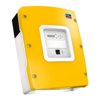
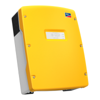
SMA Technologie AG Electrical Connection
Technical Description SI5048-11:EE4206 Page 35
1. Sheathe the cable screw connection over the ground conductor and then insert the
ground conductor into the housing of the Sunny Island 5048.
2. Install the M25 metric-thread cable screw connection (included in delivery) in the
"Grounding" cable feed-through.
- Insert the metric-thread cable screw connection into the feed-through opening.
- Screw the counter nut onto the cable screw connection thread inside the
housing and tighten it.
3. Remove the protective insulation from the conductor and fit a suitable ring cable
lug to the exposed end of the conductor.
4. Attach the conductor with the ring cable lug to the ground connection terminal and
tighten the screw firmly (torque 4.0 Nm to 5.7 Nm).
Calculating the Required Grounding Conductor Cross-section
SMA Technologie AG cannot calculate generally valid values for the required cross-
section of the grounding conductor for the external grounding of the battery. The
conductor dimensions depend on the type and size of the battery connected, the
external fuse (DC side) and the material used in the grounding conductor.
The required cross-section of a (copper) grounding conductor can be calculated using
the following formula. Trigger times, e.g. for the integrated DC circuit breaker, of about
25 ms are typical for short-circuit currents between 2000 A and 10000 A.
Exact calculation of the grounding conductor cross-section must take account of
the regionally applicable standards and guidelines (e.g DIN VDE 0100 Part
540).

 Loading...