2 PRODUCT OVERVIEW
The I/O module is integrated into the main controller.
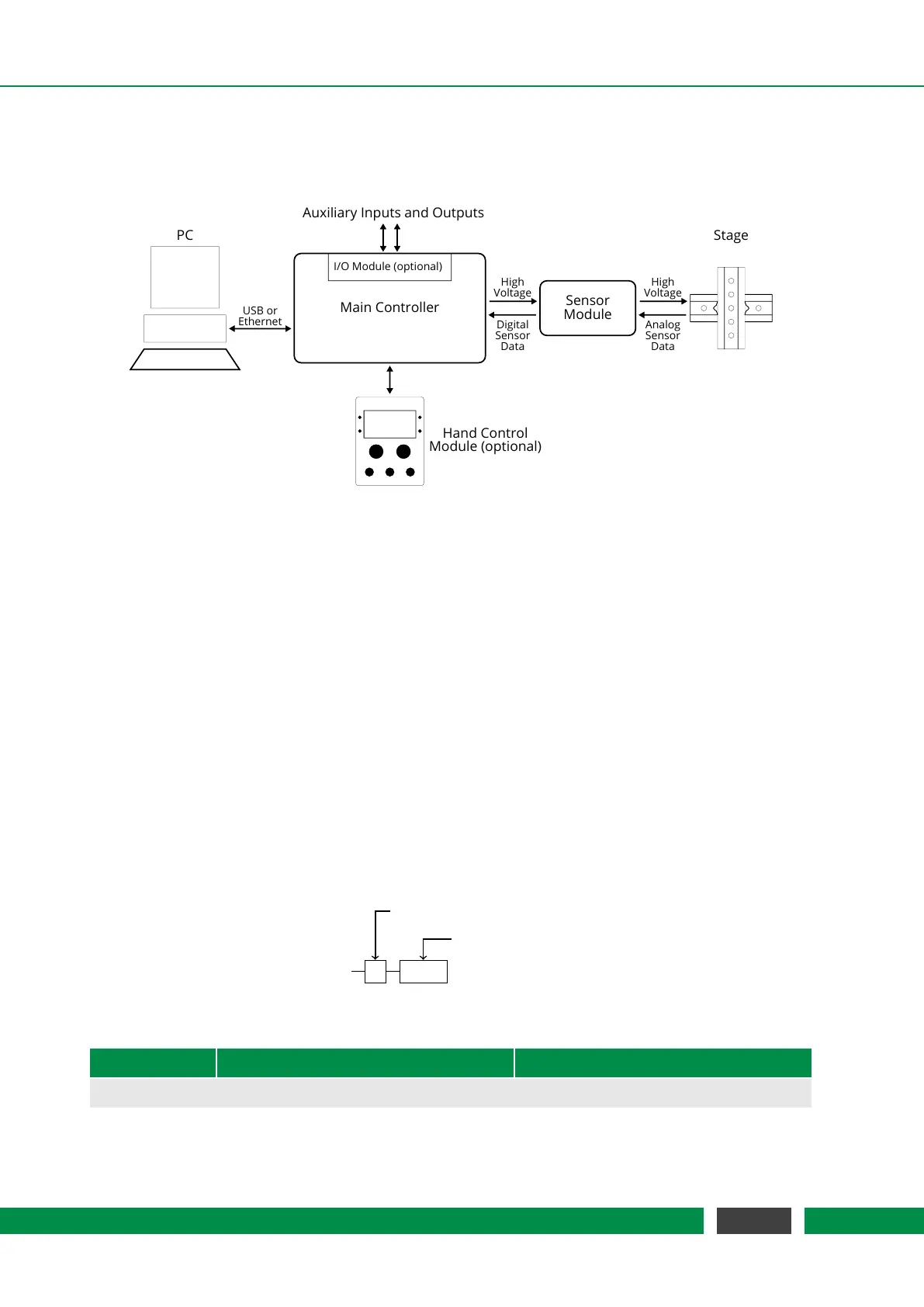
Figure 2.1 shows a structural setup of a typical MCS2 system.
Main Controller
PC
USB or
Ethernet
Sensor
Module
Stage
High
Voltage
Analog
Sensor
Data
High
Voltage
Digital
Sensor
Data
Hand Control
Module (optional)
I/O Module (optional)
Auxiliary Inputs and Outputs
Figure 2.1: Structural Setup of an MCS2 Device
Note that all external connections support hot-plugging. The controller will automatically detect
and report a changed configuration. If the connection to the PC or Hand Control Module is un-
plugged, all movements that were sent over the disconnected interface are stopped as a safety
measure.
As there is a wide range of applications, many different combinations of MCS2 main controllers
and sensor modules are configurable to meet the individual needs of our customers. Sections 2.1
and 2.2 give an overview on current models.
2.1 MCS2 Main Controller
MCS2 main controllers are available with different housing, a selectable number of channels and
an interface option which offers all the connectivity needed. The configuration of your product is
defined by the product code below and the options listed in table 2.1.
MCS2
C 0001
Housing Type
Constellation Code
Table 2.1 – Product Codes
Product Code Description Connectors
Table Top Housing (Type C)
Continued on next page
11
MCS2 User Manual