4 TECHNICAL DATA
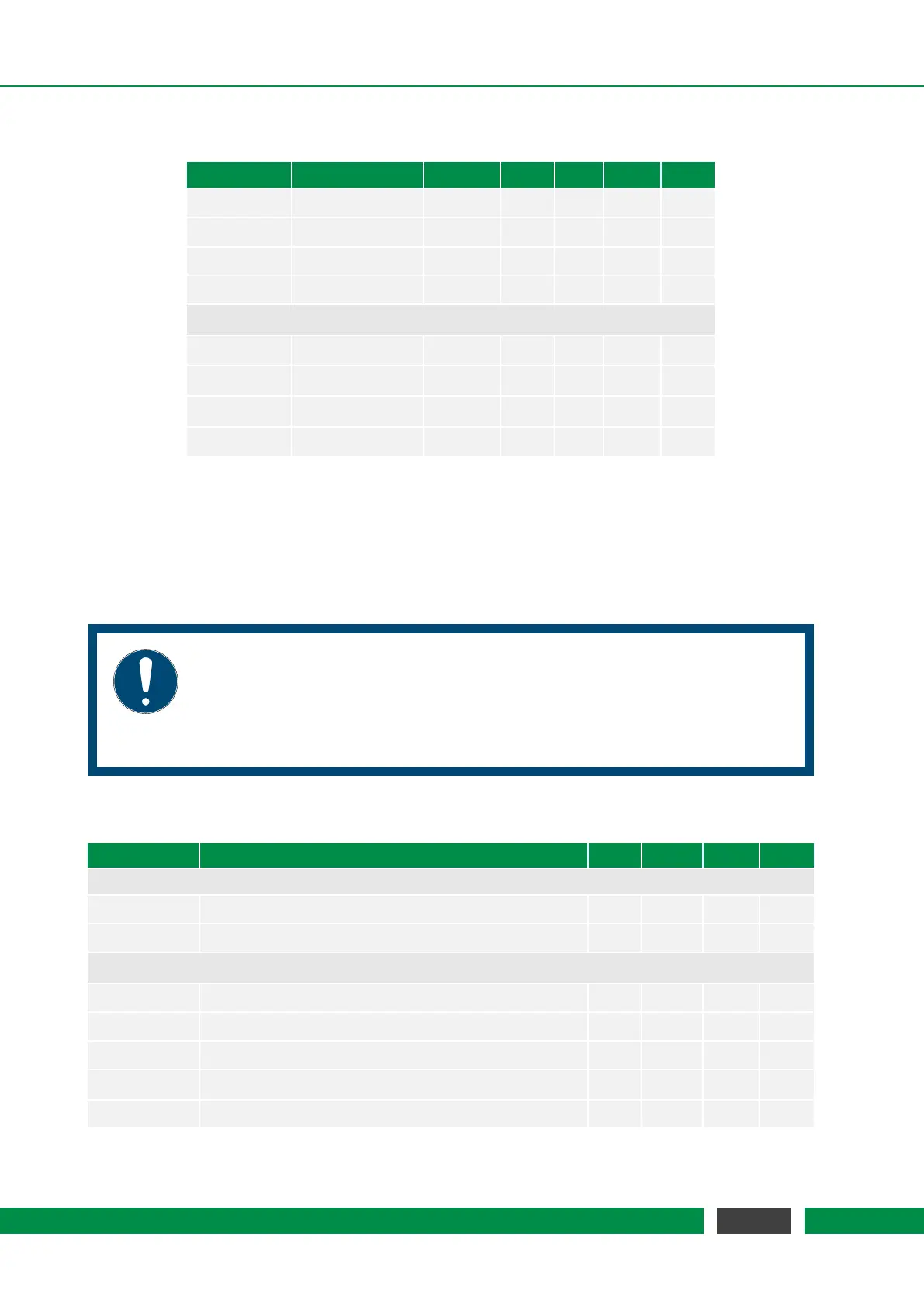
Table 4.11 – Continued from previous page
Parameter Condition Vcc MIN TYP MAX Unit
V
i
-0.3 5.5 V
V
ih
3.3V/5V 1.9 2.1 V
V
il
3.3V/5V 1.0 1.2 V
R
i
1 MΩ
General Purpose Digital Outputs
I
ol
Open Collector 700 mA
I
oh
Open Collector 2 µA
V
oh
Open Collector 24 V
R
on
Open Collector 400 mΩ
4.4.4 Auxiliary GP Analog Outputs
The analog outputs feature a DAC with 16bit resolution. All outputs are galvanically isolated to the
internal ground of the controller. The corresponding GND signals of the specific outputs should
be used to archive the best performance.
NOTICE
Note that the analog outputs may generate a short random voltage peak in the
range of ±10V while powering up or down the controller before the level stabi-
lizes at its default level of 0V. External equipment must be capable of standing
this or must be disconnected while power-up / power-down.
Table 4.12 – General Purpose Analog Outputs Specification
Parameter Condition MIN TYP MAX Unit
Common
V
iso
60 V
R
iso
10 MΩ
General Purpose Analog Outputs
V
o
-10 10 V
I
o
10 mA
R
o
10 Ω
INL Using line passing through codes 512 and 65024 ±4 LSB
DNL ±0.2 LSB
Continued on next page
31
MCS2 User Manual