4 TECHNICAL DATA
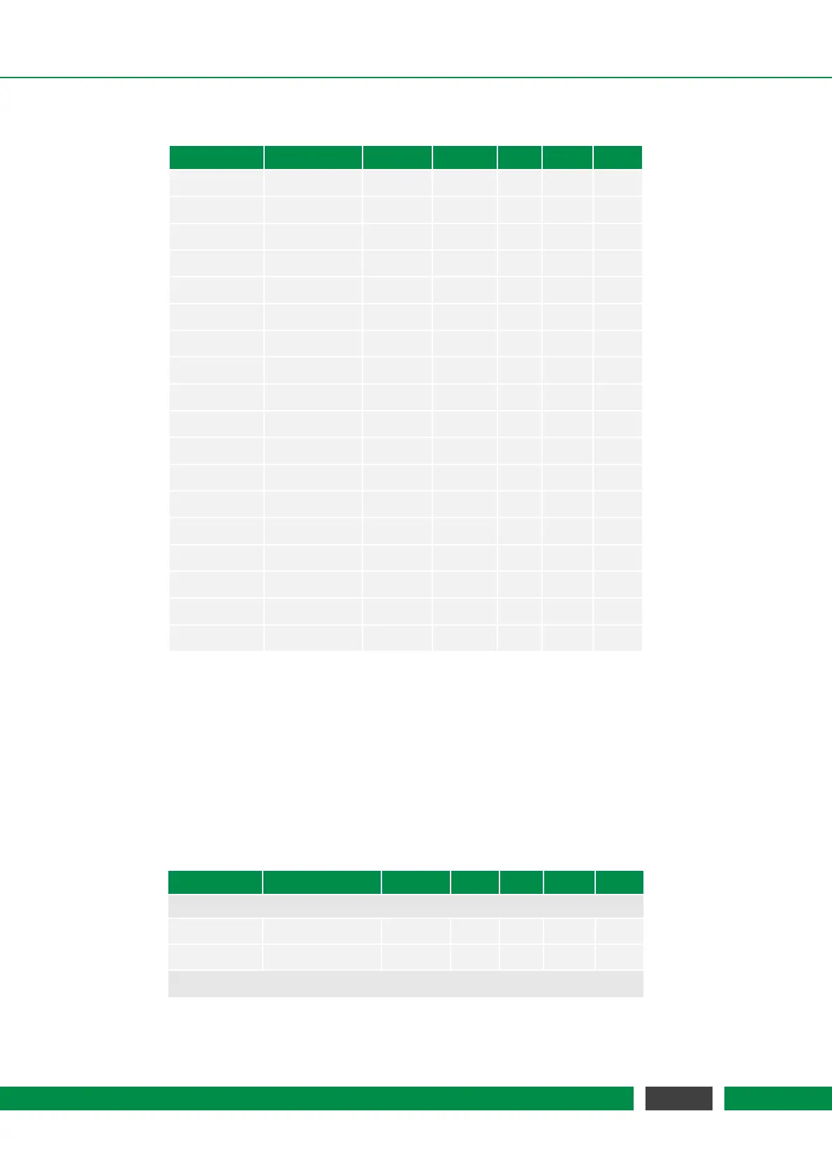
Table 4.10 – Continued from previous page
Parameter Condition Vcc MIN TYP MAX Unit
V
oh
Ioh = 20uA 3.3V/5V Vcc-0.1 V
V
oh
Ioh = 2mA 3.3V 3.05 V
V
oh
Ioh = 3mA 3.3V 2.90 V
V
oh
Ioh = 5.5mA 3.3V 2.60 V
V
oh
Ioh = 8mA 3.3V 2.50 V
V
oh
Ioh = 2mA 5V 4.75 V
V
oh
Ioh = 3mA 5V 4.60 V
V
oh
Ioh = 5.5mA 5V 4.30 V
V
oh
Ioh = 8mA 5V 4.20 V
V
ol
Iol = -20uA 3.3V/5V 0.10 V
V
ol
Iol = -2mA 3.3V 0.20 V
V
ol
Iol = -3mA 3.3V 0.26 V
V
ol
Iol = -5.5mA 3.3V 0.49 V
V
ol
Iol = -8mA 3.3V 0.71 V
V
ol
Iol = -2mA 5V 0.20 V
V
ol
Iol = -3mA 5V 0.25 V
V
ol
Iol = -5.5mA 5V 0.48 V
V
ol
Iol = -8mA 5V 0.70 V
4.4.3 Auxiliary GP Digital Inputs/Outputs
All signals are galvanically isolated to the internal ground of the controller. The general purpose
digital inputs have schmitt-trigger characteristics. Table 4.11 lists the threshold voltage levels.
The general purpose digital outputs are designed as open-collector outputs. This means that
the output logic is inverted. Writing a one to an output switches the output transistor on which
leads to a low signal level at the output pin.
Table 4.11 – General Purpose Digital Inputs/Outputs Specification
Parameter Condition Vcc MIN TYP MAX Unit
Common
V
iso
60 V
R
iso
10 MΩ
General Purpose Digital Inputs
Continued on next page
30
MCS2 User Manual