4 TECHNICAL DATA
4.2.2 D-SUB-15 Connector for Sensor Module
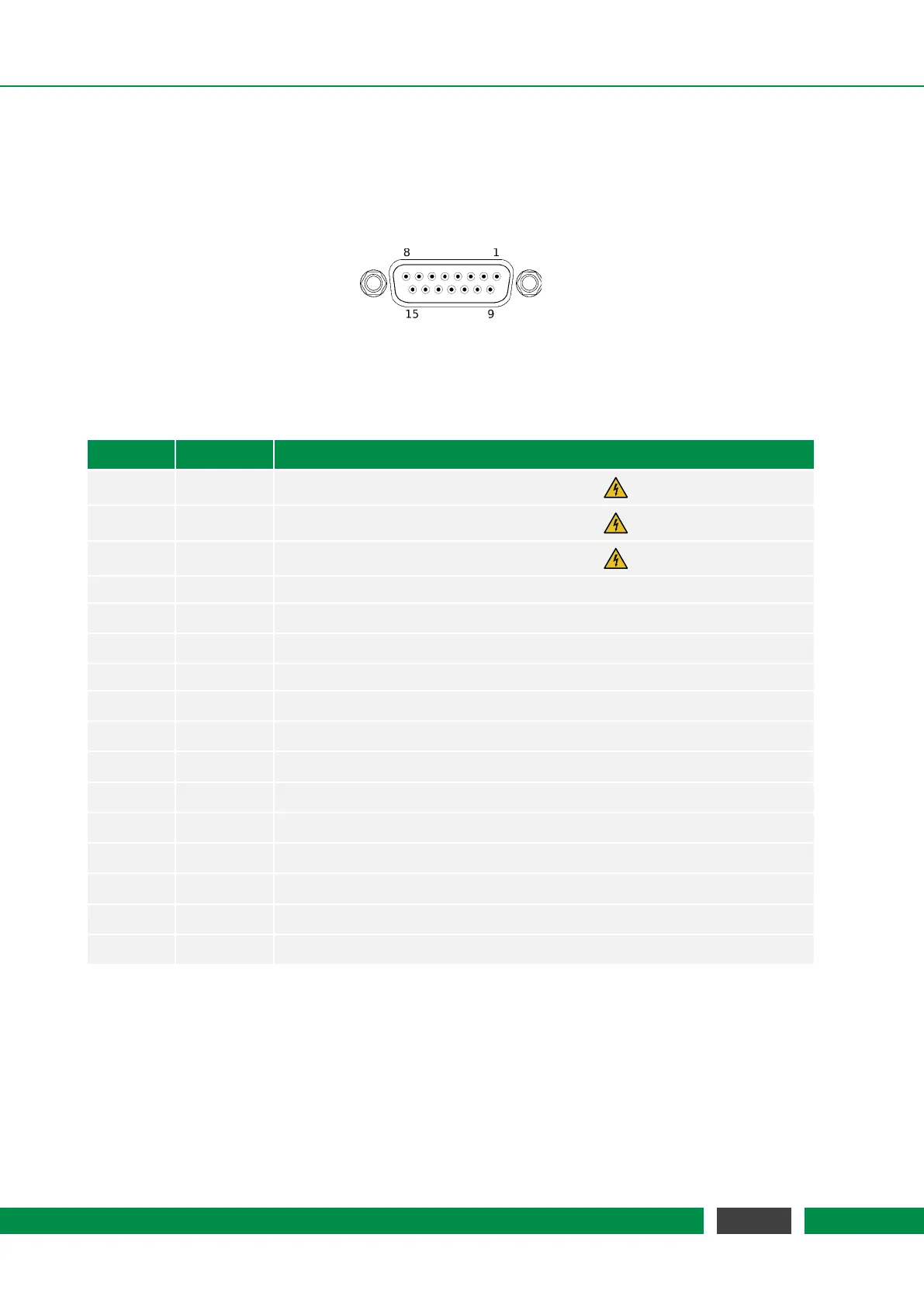
The MCS2 controller provides one or more female D-SUB-15 connectors to stick-slip positioners
via an MCS2 Sensor Module. The pin layout is described below.
D-SUB-15 connector to Sensor Module
Table 4.5 – DSUB15 Pin Assignment
Pin Signal Function
1 HV-OUT-1 Positioner driving signal, channel 1, 4, 7, ...
2 HV-OUT-2 Positioner driving signal, channel 2, 5, 8, ...
3 HV-OUT-3 Positioner driving signal, channel 3, 6, 9, ...
4 SM-GND Ground for Sensor Module and sensor
5 SM-TX-D- RS-422 D- signal from Sensor Module
6 SM-RX-D- RS-422 D- signal to Sensor Module
7 d.n.c. DO NOT CONNECT
8 EXT_STATE Internal signal lines
9 HV-GND-1 Ground for positioner driving signal, channel 1, 4, 7, ...
10 HV-GND-2 Ground for positioner driving signal, channel 2, 5, 8, ...
11 HV-GND-3 Ground for positioner driving signal, channel 3, 6, 9, ...
12 SM-TX-D+ RS-422 D+ signal from Sensor Module
13 SM-RX-D+ RS-422 D+ signal to Sensor Module
14 SyncB Internal sync line
15 SM-5V Power supply for Sensor Module, 5V DC
Shielding SM-Shield Shielding for Sensor Module and sensor
4.2.3 D-SUB-15-HD Connector for External Hand Control Module
For external Hand Control Modules the MCS2 controller provides a female D-SUB-15 high-density
connector. The pin layout is described below.
24
MCS2 User Manual