4 TECHNICAL DATA
4.3 MCS2 Sensor Module Connectors
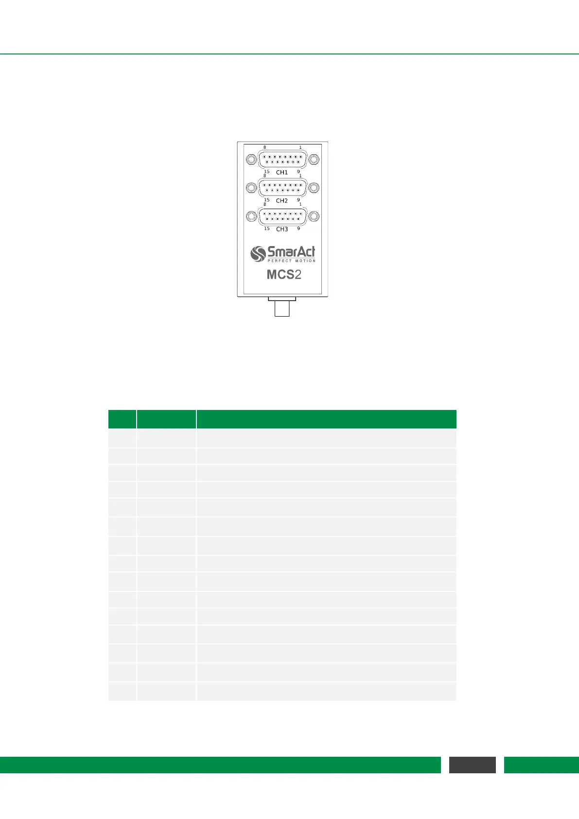
4.3.1 D-SUB-15 Positioner Connectors
Sensor Module D-SUB-15 connectors
Table 4.8 – Pin Assignment
Pin Signal Function
1 HV-OUT-x Positioner driving signal, channel x
2 d.n.c. DO NOT CONNECT
3 d.n.c. DO NOT CONNECT
4 S-GND Ground for sensor
5 S-SIN+ sin+ signal from sensor
6 S-COS+ cos+ signal from sensor
7 S-REF+ ref+ signal from sensor
8 d.n.c. DO NOT CONNECT
9 HV-GND-x Ground for positioner driving signal, channel x
10 d.n.c. DO NOT CONNECT
11 d.n.c. DO NOT CONNECT
12 S-SIN- sin- signal from sensor
13 S-COS- cos- signal from sensor
14 S-REF- ref- signal from sensor
15 S-VCC Power supply for sensor
28
MCS2 User Manual