4 TECHNICAL DATA
*The HV-OUT-x signals are identical to the HV-OUT-x signals from the MCS2 controller.
4.4 MCS2 Electrical Specifications
4.4.1 Positioner Driver Output
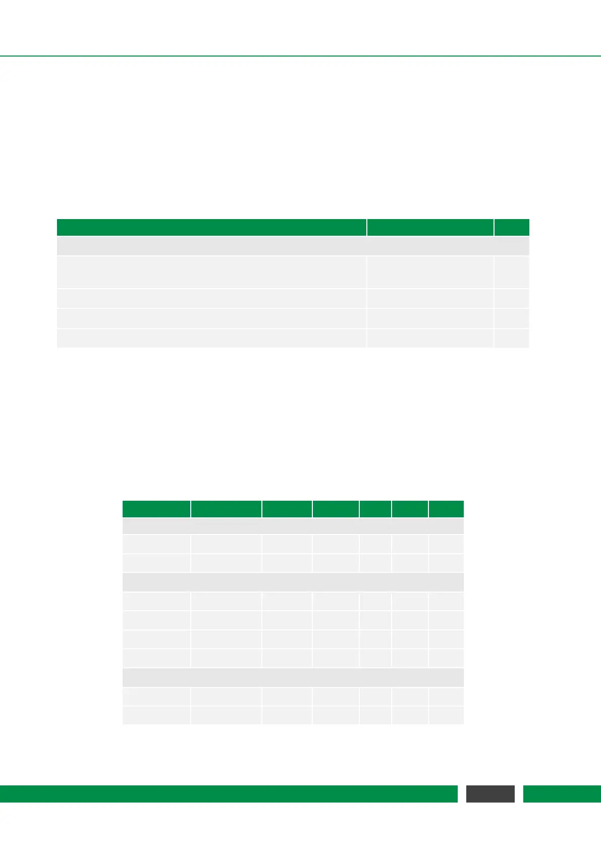
Table 4.9 – Driver Output Specification
Parameter Value Unit
Driving Signal (HV-OUT-x)
Signalform sawtooth (step mode)
constant (scan mode)
Output voltage range 0 to 100 V
Average current per channel 200 mA
Peak current per channel, < 10 µs, max. speed 20 A
4.4.2 Auxiliary Fast Digital Input/Outputs
All signals are galvanically isolated to the internal ground of the controller. The digital device
input has schmitt-trigger characteristics. Table 4.10 lists the threshold voltage levels. The output
voltage level of the fast digital outputs can be configured to 3.3V or 5V by software. This setting is
global for all digital outputs. Note that the digital outputs are in a high-impedance state by default,
therefore the output driver must be explicitly enabled.
Table 4.10 – Fast Digital Input/Output Specification
Parameter Condition Vcc MIN TYP MAX Unit
Common
V
iso
60 V
R
iso
10 MΩ
Digital Device Inputs
V
i
-0.3 5.5 V
V
ih
3.3V/5V 1.9 2.1 V
V
il
3.3V/5V 1.0 1.2 V
R
i
1 MΩ
Fast Digital Outputs
I
o
3.3V 8 mA
I
o
5V 3 mA
Continued on next page
29
MCS2 User Manual